background image

2

36" (914mm) Recommended 

30" (762mm) Min. 

25"

(635mm)

30 1/16" 

(764mm)10"

(254mm)

14"

(356mm)

Hood

30" (762mm) 

Min.

10" (254mm) Min.

to combustible side

walls above the range

(both sides)

13"

(330mm)

Max.

1

10"

(254mm)

Top of  

finished

counter

Vertical 

combustible

surface

18" (457mm) 

Min.

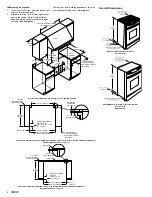
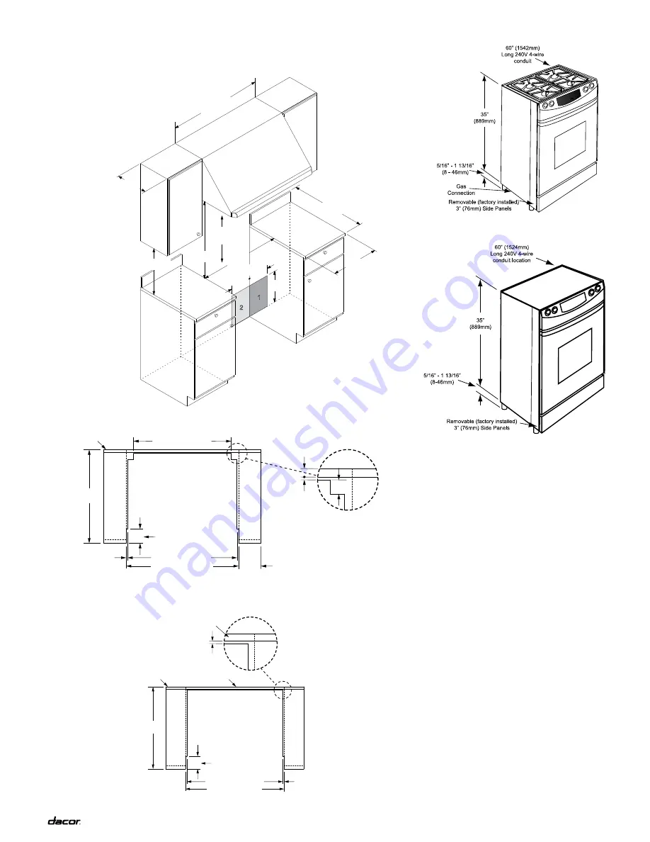
Overall Cabinet dimension and Clearance to Combustible Surfaces

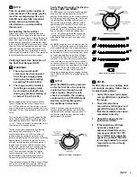
downdraft ERV30 with Slide-In, Self-Rimming Installation using 3” Side Panels ( Numbers ARSR30 and ARSL30),   

with Backguard Removed - Top View

Slide-In, Self-Rimming Installation using 3” Side Panels (Part Numbers ARSR30 and ARSL30),  

Backguard Removed - Top View

Overall dimensions

RSd30 Overall dimensions (dual Fuel)

Isometric View

RSE30/MRES30 Overall dimensions (All Electric)

Isometric View

(RSE30 Shown)

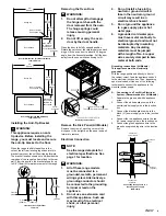
Utilities may be located:

1.  In the lower left corner of the adjacent right 

cabinet. (Recommended)

2.  Alternate location, in the lower right corner 

behind the range. (Note: Some building 

departments do not permit concealing gas 

valves behind appliances.)

Contact your local building department to verify 

compliance with local code interpretation.

1/4" (6mm)

Min. flat ledge

28 11/16" (729mm)

11/16"

(17mm)

29 5/8" (752mm)

Rear wall

25"

(635mm)

Adjust for backsplash

thickness

13/16" to 4 1/4" 

(21 - 108mm)

Backsplash

Vertical

non-combustible

surface rear wall

27 13/16" 

(706mm)

29 1/4" (743mm) 

13/32" (10mm) 

30 1/16" (764mm) 

Countertop overhangs cabinet 

10" (254mm) Min.

to combustible side

walls above the range

(both sides)

27 7/8" (708mm) 

Adjust for backsplash 

over 3/4" thick 

from 13/16" to 3 13/16"

(21 - 97mm) 

Backsplash

thicker than 

3/4" (19mm) 

1/4" (6mm) 

Min. flat ledge 

Vertical 

non-combustible

surface rear wall 

2 13/16" 

(71mm)

Summary of Contents for Preference RSE30

Page 1: ...eparation Page 2 3 STEP 6 Overall dimensions Page 3 4 STEP 7 Installing the anti tip bracket Page 4 STEP 8 Removing the oven door Page 4 STEP 9 Removing the kick panel Page 4 STEP 11 Electrical connec...

Page 2: ...r to Electrical Requirements 11 Install or locate this appliance only in accordance with these installation instructions 12 Use this appliance only for its intended use as described in this manual Do...

Page 3: ...ower supply preheat times and cavity temperature recovery times will be increased slightly Gas and Electrical Rough In Locations NOTE The shaded areas shown in the illustrations denotes the location o...

Page 4: ...ic View RSE30 Shown Utilities may be located 1 In the lower left corner of the adjacent right cabinet Recommended 2 Alternate location in the lower right corner behind the range Note Some building dep...

Page 5: ...nti Tip Bracket WARNING This appliance require an anti tip device Before installing the range you must locate and secure the anti tip bracket to the floor When the range is slid into position in the c...

Page 6: ...es to the OFF position Turn on gas supply and check all lines and connections for gas leaks using a soap and water solution Do not use a flame to check for leaks After verifying that there are no gas...

Page 7: ...conds the element should be fully energized and glowing red Verify that the residual heat indicator light comes on in conjunction with the proper element within approximately 30 seconds Return the kno...

Page 8: ...his book are the copyright property of Distinctive Appliances Inc Neither this book nor any information or images contained herein may be copied or used in whole or in part without the express written...

Reviews: