background image

3

Installation Specifications
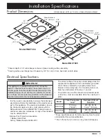
Product Dimensions

36”

(91.4 cm)


2

34” 

(86.4 cm)

1

19” 

(48.3 cm)

1

21”

(53.3 cm)


2

3/16” (4.8 mm)

Glass thickness:

3 7/8” 

(9.8 cm)

30”

(76.2 cm)


2

28”

(72.4 cm)

1

19”  

(48.3 cm)

1

21”

(53.3 cm)

2

3 7/8” 

(9.8 cm)

3/16” (4.8 mm)

Glass thickness:

 IMPORTANT

This appliance is provided with electrical connection 

leads in a flexible metal conduit. These leads may be a 

smaller gauge than the standard household wiring of the 

dedicated supply circuit, but they are suitable for connec-

tion to these circuits under the jurisdiction of the National 

Electric Code, and/or the local inspection authority.

• 

It is the owner’s responsibility to ensure that a licensed 

electrician performs the installation of the electrical sup-

ply for this appliance. The electrical installation, includ-

ing minimum supply wire size, must comply with the 

National Electric Code ANSI/NFPA 70 (latest revision) 

and local codes and ordinances. A copy of the standard 

may be obtained from:

National Fire Protection Association 

1 Batterymarch Park 

Quincy, Massachusetts 02269-9101

Electrical Specifications

• 

The correct voltage, frequency and amperage must be 

supplied to the appliance from a dedicated, grounded, 

circuit that is protected by a properly sized circuit 

breaker or time-delay fuse. If a time-delay fuse is uti-

lized, fuse both sides of the line (L1 and L2).

• 

The junction box and the remote circuit breaker panel 

or fuse box, must be accessible when the cooktop is in 

place.

Model

Total Connected 

Load*

Dedicated Circuit 

Required

RNCT304

31.0 Amp. 

(7.44 kW)

240 Vac, 60 Hz.  

3 wire** 40 Amp.

RNCT365

45.0 Amp. 

(10.56 kW)

240 Vac, 60 Hz.  

3 wire** 50 Amp.

* These specifications are for reference only. See the prod-

uct data label for exact specifications.
** Two 120 Vac hot (L1 and L2), one ground (all copper).

Model RNCT304

Model RNCT365

All tolerances: ±1/16 (±1.6 mm), unless otherwise stated.

1

Chassis depth is 1/2” wider/deeper at base of glass cooking surface assembly.

2

Cooking surface overhangs top of chassis by 3/4” (1.9 cm) in front, back and on both sides.

Summary of Contents for RNCT304

Page 1: ...Installation Instructions Induction Cooktop Models RNCT304 and RNCT365 Part No 107240 Rev C...

Page 2: ...he customer Customer Keep these installation instructions for future reference and the local electrical inspector s use 2013 Dacor all rights reserved Customer Service Information If You Need Help If...

Page 3: ...low the cooktop warning Persons with a pacemaker or other medical device should use caution when standing near an induction cooktop when it is in use The electromagnetic field generated by an inductio...

Page 4: ...e or unattended in the area around the cooktop Do not allow children to play with the controls Do not store items of interest to children above or on top of the cooktop Children could be burned or inj...

Page 5: ...ances A copy of the standard may be obtained from National Fire Protection Association 1 Batterymarch Park Quincy Massachusetts 02269 9101 Electrical Specifications The correct voltage frequency and a...

Page 6: ...es and ordi nances during planning and installation Contact your local building department for further information To reduce the risk of a fire hazard cooktop malfunc tion and or damage to the applian...

Page 7: ...ick aluminum or 020 inch thick copper 2 Distance to combustible side wall both sides 2 7 8 7 3 cm min from edge of cutout 2 1 4 5 7 cm min from edge of cooking surface 3 This specification not applica...

Page 8: ...pth from the product dimensions in the down draft vent installation instructions Additional sealing will be required between the cooktop chassis and the downdraft vent due to the dif ference in inset...

Page 9: ...to the circuit to which the cooktop will be connected at the circuit breaker panel or fuse box 2 Feed the appliance conduit into the junction box and attach it using a UL certified strain relief 3 Dep...

Page 10: ...y pipe or hot water pipe If connecting the ground wire to a grounded cold water pipe connect it using a separate copper grounding wire No 10 minimum and a clamp with an external grounding screw The gr...

Page 11: ...cooktop does not operate properly follow these troubleshooting steps Verify that power is supplied to the cooktop Check for proper electrical connections Repeat the above tests If the appliance still...

Page 12: ...Dacor 14425 Clark Avenue City of Industry CA 91745 Phone 800 793 0093 Fax 626 403 3130 www dacor com...

Reviews: