background image

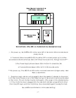
System Display Messages

The System Controller has an LCD display which has several functions. One is to 
allow the user to see menu options for programming the system, and the other is for 
displaying error messages in the event that the controller has encountered a 
problem. In some cases, if the controller senses that the door has become 
obstructed, the system will shut down and a reboot is required.  The error messages 
should give a general idea of what the problem may be and the information below 
should offer a remedy to correct the error.  In the event that the door stops working, 
prior to turning off the power to the Master Controller remove the top cover panel 
and check for any error messages on the LCD.  

Bootup Routine

Upon powering up the controller, the LCD will display several messages that relate to 
the boot up diagnostic routine. The boot up messages are shown in the order 
below:

1. Software Revision    (ie  REV3.03.027)
2. Current temperature in Fahrenheit. to 4 decimal places (ie 74.0125F)

The temperature readout is not of any significant value to the user, except in cases 
of troubleshooting the information may be requested by Dado Door.

3. ENCODER TEST: Encoder Passed or Encoder Failed.

The encoder is a sensor 

attached to the motor that allows the system to know very precisely where the 
motor and door are at all times. If the encoder has been damaged or the cable 
that connects the system controller to the motor (Motor Logic port) is disconnected, 
then the encoder test will report Encoder Failed. If the system finds that the encoder 
is operating as it should, it will report Encoder Passed. The system cannot run unless 
the encoder is tested to be connected and working properly. If you get this error on 
power up, the typical issue is that the MTR Logic cable is not connected, or the Max 
Torque is too low.  See troubleshooting guide for more info.

4. Homing   

If the system has booted up and the encoder diagnostic has passed, 

then the screen will show the message HOMING....   During this phase the door 
should be moving very slowly towards the fully open position, and the door should 
press in the Home Switch located on the track.  

5. Jog Reverse 

  After pressing in the Home Switch, the screen will show the message 

"Jog Reverse".  During this phase, the door will move back off of the Home Switch so 
that the door no longer is pressing the switch in.  

6. Ready 

  Assuming that everything went well during the bootup routine, the screen 

will show the message "Ready" indicating that the door is ready for normal 
operation.  If any other error messages are shown, please consult the error messages 
section and contact Dado Door if assistance is needed.

16

Summary of Contents for Door Master Controller

Page 1: ...Manual Copyright 2013 All rights reserved No unauthorized duplication distribution or online posting without prior written consent from Dado Door LLC Dado Door LLC and the Dado Logo are registered tr...

Page 2: ...Motor Driver Fault Error Troubleshooting 20 Advanced Motor Driver Fault Error Troubleshooting Cont d 21 Initial Calibration and Setup 22 Initial Calibration and Setup cont d 23 Error Messages 24 Error...

Page 3: ...roller contains a simple and easy to follow menu directory of settings When changing a setting they are stored permanently This manual will cover all aspects of the menu It is advised that the install...

Page 4: ...E fully open quickly turn off the power If the door begins the homing process towards the CLOSED position then the belt has been installed in reverse It is advised that when powering the system up for...

Page 5: ...formation needed to set up the parameters Buttons Explained Move up or down the Main Menu Add or subtract from a number or select Yes No fields CURSOR Cycle the cursor through a menu item with more th...

Page 6: ...gs Factory settings Do not change 4 BYPASS MODE If required at power ON the user can immediately PRESS and HOLD down the Setup Mode Button until the Main Menu appears this will bypass the diagnositcs...

Page 7: ...erial communication Port 8 RS485 interface duplicate for daisy chain Motor 3 Phase Power Leads Connection to the Brushless DC motor power using 26VDC is made with a 3 condutor 18G specially prepared c...

Page 8: ...y the port that will be used as a Locking Touch Screen inside the room Port A it typically the outside Touch Screen Auto Home Upon each power up the system automatically moves towards a Home switch wh...

Page 9: ...configured to receive input from any low voltage source for remote control such as a fire alarm contact closure PiNG Proximity Sensor Option The Ping Sensor is a small device offered by Dado Door that...

Page 10: ...system against overload due to an obstruction during the Homing phase The parameters may need to be adjusted to account for the weight speed and friction of each door by the user at the time of insta...

Page 11: ...ng thus a higher Trip Level will be required to avoid false trips Each time the speed is adjusted in the menu the Trip Levels will need to be adjusted as well for optimal retraction If you have set th...

Page 12: ...where the motor door are in a highly precision manner The Set Close Position value shown in the display will equate to approximately 1 500 As an example if the value says 5000 then calculate 5000 500...

Page 13: ...ressure on the door during the closing motion Above a certain pressure on the door the door will auto retract Closing Trip Level In some cases during the last couple of inches of travel closing as the...

Page 14: ...mber means the factor will be larger and will take longer to slow the door to a stop To cause the door to take longer to accelerate to full speed choose a higher accel factor Shorter values produce a...

Page 15: ...opposite direction while the arrows are pressed Due to the fact that there are numerous ways a system can be set up these arrows may not always reflect the direction that the door is actually moving i...

Page 16: ...ned on the offset value is used for the fully open position The value in the menu is approximately 1 500 So for example to create a 1 2 offset put the offset value at 250 The door should move as the s...

Page 17: ...controller The Destination number will always be 0 by default System Input Configuration The system controller has a number of options for controlling the door On the top of the enclosure are the con...

Page 18: ...attached to the motor that allows the system to know very precisely where the motor and door are at all times If the encoder has been damaged or the cable that connects the system controller to the m...

Page 19: ...Fault LED on the motor driver board is lit right away then there is a problem 1 The Motor Logic cable is not plugged in from the Master Controller to the motor 2 On the motor there is a set of five w...

Page 20: ...any wires out of a pair Each end of the CAT5 cable should be identical colors not mirrored colors When the connection problem is resolved on power up the motor driver board will only have the Green PW...

Reviews: