16-11
Hydraulic Brake
Installation
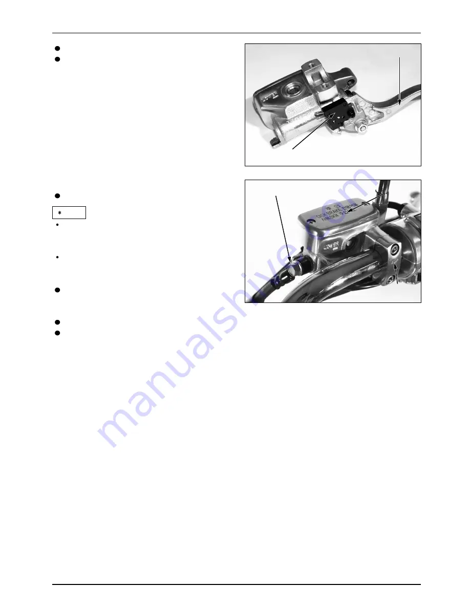
Place the master cylinder into the handle bar.
Install the holder with the “UP” mark facing up.
Align the end of master cylinder with the
punch mark on the handle bar.
Tighten the upper bolt first, then tighten the
lower bolt.
Install the brake hose to the master cylinder
with the hose bolt and two sealing washers.
Torque: 3.4kgf-m
Connect the stop switch wires to the switch.
Fill and bleed the front brake hydraulic system.
Install the boot into master cylinder.
Install the rear mirror, brake lever and stop
switch.
Torque: Brake Lever Pivot Bolt
1.0kgf-m
Master Cylinder
Master Cylinder
Master Cylinder
Master Cylinder
Master Cylinder
Master Cylinder
Master Cylinder
Master Cylinder
Master Cylinder
Master Cylinder
Master Cylinder
Master Cylinder
Master Cylinder
Brake Hose Bolt
Brake Hose Bolt
Brake Hose Bolt
Brake Hose Bolt
Brake Hose Bolt
Brake Hose Bolt
Brake Hose Bolt
Brake Hose Bolt
Brake Hose Bolt
Brake Hose Bolt
Brake Hose Bolt
Brake Hose Bolt
Brake Hose Bolt
“UP” Mark
“UP” Mark
“UP” Mark
“UP” Mark
“UP” Mark
“UP” Mark
“UP” Mark
“UP” Mark
“UP” Mark
“UP” Mark
“UP” Mark
“UP” Mark
“UP” Mark
NOTE
Brake Lever
Brake Lever
Brake Lever
Brake Lever
Brake Lever
Brake Lever
Brake Lever
Brake Lever
Brake Lever
Brake Lever
Brake Lever
Brake Lever
Brake Lever
Brake Right Switch
Brake Right Switch
Brake Right Switch
Brake Right Switch
Brake Right Switch
Brake Right Switch
Brake Right Switch
Brake Right Switch
Brake Right Switch
Brake Right Switch
Brake Right Switch
Brake Right Switch
Brake Right Switch
Summary of Contents for DAYSTAR VL125E
Page 12: ...1 11 General Information...
Page 13: ...1 12 General Information...
Page 14: ...1 13 General Information...
Page 15: ...MEMO...
Page 23: ...MEMO...
Page 39: ...Fuel System 4 0...
Page 91: ...MEMO...
Page 96: ...MEMO...
Page 97: ...7 0 Clutch Gearshift...
Page 110: ...MEMO...
Page 111: ...8 0 A C Generator Starter Clutch...
Page 120: ...MEMO...
Page 121: ...9 0 Cylinder Head Valve...
Page 138: ...MEMO...
Page 139: ...10 0 Cylinder Piston...
Page 147: ...11 0 Crank Case Transmission Crankshaft 1 2kgf m 12N m 1 1kgf m 11N m...
Page 159: ...12 0 MEMO...
Page 166: ...13 5 MEMO...
Page 167: ...14 0 Front Wheel Front Fork Steering...
Page 189: ...15 0 Rear Wheel Rear Brake Suspension...
Page 201: ...16 0 Hydraulic Brake...
Page 213: ...17 0 Charging System Battery Regulator Rectifier Fuse Battery AC Generator...
Page 221: ...18 0 Ignition System A C Generator Spark Plug Ignition Coil ECU...
Page 226: ...18 5 Ignition System...
Page 227: ...18 6 MEMO...
Page 228: ...19 0 Electric Starter Starter Motor Battery Starter Magnetic Switch...
Page 235: ...MEMO...
Page 236: ...20 0 SERVICE Lights Switches Horn...
Page 247: ...MEMO...
Page 248: ...21 1 Wiring Diagram 21 Wiring Diagram...
Page 249: ...21 2...


