background image

No.4 Business Building-2707, China Central Place
Chaoyang District, Beijing-100021, China

Email:info@daelim-electric.com

北 京 大 林 绿 源 环 保 科 技 有 限 公 司

BEIJING DAELIM GREEN EP TECH CO., LTD.

8. Factory Testing

CAUTION:

The information below is not intended to be as a guideline for testing transformers, please refer to

IEE/ANSI C57.12.90-2006 and

ANSI/NETA ATS-2009

for more details.

8.1 Routine Tests

Ratio

The turn ratio of a transformer is the ratio of the number of turns in the high-voltage winding to that in the

Lowvoltagewinding.Whenthetransformerhastaps,theturnratioshallbedeterminedforalltapsandfor

the full winding.

Note: The ratio test can also be used to test

polarity, phase relation, and phase sequence.

Winding Resistance

Resistance measurements are of fundamental importance for the calculation of the

2

R component of

conductorlosses and calculation of windingtemperatures at the end of atemperature rise test.

No Load and Excitation Current

No-load (excitation) losses are losses that are incident to the excitation of the transformer. No-load losses

include core loss, dielectric loss, conductor loss in the winding due to excitation current, and conductor loss

due to circulating current in parallel windings. These losses change with the excitation voltage.

Excitationcurrent(no-loadcurrent)isthecurrentthatflowsinanywindingusedtoexcitethetransformer

whenallotherwindingsareopen-circuited.Itisgenerallyexpressedinpercentoftheratedcurrentofthe

winding in which it is measured. The no-load losses consist primarily of the core loss in the transformer core,

which is a function of the magnitude, frequency, and waveform of the impressed voltage. No-load losses also

varywithtemperatureandareparticularlysensitive todifferencesin waveform;therefore,no-load loss

measurements will vary markedly with the waveform of the test voltage.

Load Losses and Impedance Voltage

The load losses of a transformer are losses incident to a specified load carried by the transformer. Load losses

include

2

R loss in the windings due to load current and stray losses due to eddy currents induced by leakage

flux in the windings, core clamps, magnetic shields, tank walls, and other conducting parts

Theimpedancevoltageofatransformeristhevoltagerequiredtocirculateratedcurrentthroughoneoftwo

specified windings when the other winding is short-circuited, with the windings connected as for rated voltage

Summary of Contents for GREEN EP TECH

Page 1: ...District Beijing 100021 China Email info daelim electric com BEIJING DAELIM GREEN EP TECH CO LTD Operation Maintenance Manual SinglePhase ThreePhasePad mountLiquid CompartmentalTransformer Filled KVA...

Page 2: ...age for more than 90 days 7 3 3 Removable Radiators 7 4 Installation 7 4 1 Pre service inspection 7 4 2 Location Consideration 8 4 3 Mounting the Transformer 8 4 4 External Connection 8 Ground Connect...

Page 3: ...ing 27 Bay O Net Fuses 27 Bay O Net fuse replacement instruction Fig 17 B 28 Dry Well Canister Fuses 28 Non Loadbreak Dry Well Canister Fuse replacement instruction Fig 18 B 29 Loadbreak Dry Well Cani...

Page 4: ...usiness Building 2707 China Central Place Email info daelim electric com Chaoyang District Beijing 100021 China BEIJING DAELIM GREEN EP TECH CO LTD 9 2 Routine Inspection 33 9 3 Dielectric Fluid Sampl...

Page 5: ...al injury hazards Obey all safetymessagesthat follow thissymbol to avoid possibleinjuryor death Safety Instructions WARNING A potential risk exists if operating instructions are not followed which cou...

Page 6: ...eightreceipt Da el i m Industries ships most units FOB Point of Manufacture and it is the customer s responsibility to file a claim against the carrier Note Ifacceptanceofthetransformerismadeanddamage...

Page 7: ...lacewhereaccessibilitytoacraneorother overheadliftingdeviceislimitedornotavailable Iftheunitmustberolled insurethattheareaislevel free from obstructions and debris and is of sufficient strength and th...

Page 8: ...r assemblies shouldnever be stored directly on the ground or in areas in which water could collect near sealed openings 4 Installation 4 1 Pre service inspection ELECTRICALSHOCK Neverattempttochangeco...

Page 9: ...unted Pressure relief device PRD also referred toas Explosion Reliefdevice CAUTION Check with local authorities in the intended installation area to verify compliance of any and all applicable laws 4...

Page 10: ...ndedandthetransformeris connectedtothepowerdistributionsystem thenthetankshouldbe regardedasenergized Anenergized tankisextremelydangerous Contactwithanenergizedtank canshock burn or causedeath Daelim...

Page 11: ...turallyexpandandcontractcausingthegasfilledheadspaceinsidethetanktofluctuateinpressure CAUTION Before performing any kind of service which may include but is not limited to opening the tank or inspect...

Page 12: ...rader Valve Fig 4 B is provided to facilitate addition of dielectric fluid and Nitrogen to the tank 5 3 Drain Valve and Fluid Sampler TheDrainValveandFluidSampler Fig 5 isprovidedtofacilitatesamplingo...

Page 13: ...htseparationbetweentheinterioroilandtheoutsidetominimize potential leaks Daelim utilizes several different brands and models of liquid level gauges depending on the application Transformers can be sup...

Page 14: ...dneedle maximumindicator can be reset by turning the knob on the front of the gauge face The temperature gauge consists of a long thermocouple that extends into the tank inside a protective thermocoup...

Page 15: ...armed by a consistent negative pressure for example if it s winter time In Wisconsin it will probably be negative for the duration of the season However if the gauge consistently readszeroanddoesnotap...

Page 16: ...Valveasshownin Fig 3 whichonlyreleasespressureslowlytoaccountforthermal expansionandcontraction APRDiscovermountedandequippedwithaspringloadeddiaphragmthatis factorysettoopenatapredeterminedpressurele...

Page 17: ...l in relay ThisRPRR Fig 10 isadevicefordetectionofsuddenpressureeventsbasedontherateofpressurerisein Thetransformer Whenadangerous pressurerise hasbeendetected therapidpressurerise relay RPRR will cha...

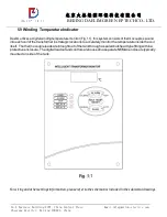
Page 18: ...his system consists of thermocouples wound intoeachcoilofthetransformerinstrategiclocationstoaccuratelymonitorthetemperatureinsidethecoil itself Thethermocoupleleadsarebrought outofthetankthroughaseal...

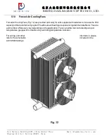
Page 19: ...ided optionally for units supplied with radiators to increase the KVA capacityofthetransformerbyupto25 withoutoverheatingorexperiencingdetrimentaleffects Thesize andnumberoffanscanvary dependingonthea...

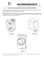
Page 20: ...ormers may be equipped with CT s for various reasons such as metering or relaying they also may be equipped with meters mounted on the transformer Different types and classes of CT s are used accordin...

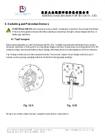
Page 21: ...tches 6 1 Tap Changers ExternallyoperatedNo LoadTapchanger NLTC Fig 14A B isprovidedforalltransformers unless otherwise specified to change from one operating voltage to another Typical taps are confi...

Page 22: ...nsformer secondary connected equipment verify that all transformer secondaryterminalshavezerovoltageandgroundthetransformersecondaryterminalsfollowing industryacceptedsafegroundingpractices Groundings...

Page 23: ...unt transformerstoselectthefeedsource openorclosethefeed thruloopandopenorclosethetransformer The spring loaded activating mechanism ensures quick load break action and positive contact engagement thr...

Page 24: ...er nameplate WARNING The transformer must be de energized and grounded before dual voltage switch is operated Attempting to change dual voltage switch on an energized transformer may result in damage...

Page 25: ...eplate WARNING The transformer must be de energized and grounded before dual voltage switch is operated Attempting to change dual voltage switch on an energized transformer may result in damage to the...

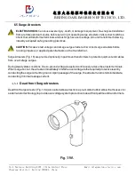
Page 26: ...ct surge arresters before running impulse or applied potential tests on the transformer Surge Arresters Fig 16 are provided optionally in padmount transformers to protect equipment and cables from ove...

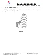
Page 27: ...100021 China Email info daelim electric com BEIJING DAELIM GREEN EP TECH CO LTD Live front SurgeArresters Live front Surge Arrester Fig 19 B is a polymer that houses a metal oxide Varistor to provide...

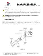
Page 28: ...d Donotre energizesuspectedfailedequipment Afterinstallingfuses energizetransformerfroma remote upstreamsource WARNING Never attempt to remove fuses with pressure on the tank Severe burns and personal...

Page 29: ...y O Net housing 5 Draw fuse holder out quickly 8 10 inches to interrupt load 6 Wait several seconds for fluid to drain from the fuse holder and remove from housing 7 Remove fuse cartridge from fuse ca...

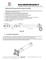
Page 30: ...4 set screws 3 Attach a hot stick to the fuse holder eye and pull out 4 Draw fuse holderout 5 Replace the fuse and reinsert the fuse with the fuse holder 6 Assemble by tightening 4 set screws Loadbre...

Page 31: ...Solubility in water negligible 0 1 Viscosity 9 3TO9 5CsTat40 C 7 2 High Fire Point Dielectric fluid Padmount transformers filled with High Fire Point Dielectric fluid typically use Envirotemp FR3 flui...

Page 32: ...in the winding due to excitation current and conductor loss duetocirculating current in parallelwindings These losseschange withthe excitation voltage Excitationcurrent no loadcurrent isthecurrentthat...

Page 33: ...ngs to ground or between individual windings Insulation resistance tests are commonly measured in mega ohms or may be calculated from measurements of applied voltage and leakage current Temperature Ri...

Page 34: ...conditions of the site into consideration Salty damp or otherwise corrosive environments will require shorter inspection intervals than dry and mild conditions Periodicallycheckbetweentheradiators ife...

Page 35: ...ectric Fluid Sampling Dielectricfluid samplesshouldbetaken atleastonan annualbasisand analyzed byDGA Dissolved Gas Analysis RoutineDGAtestingisoneofthebestmethodsofdeterminingthe Health ofatransformer...

Reviews: