EMS(Engine Management System)
5-20
Checking Procedure
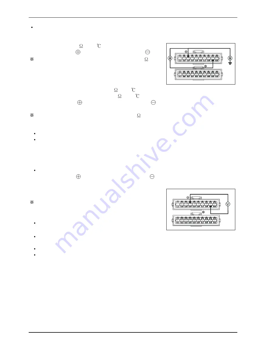
6) Check continuty between the Sensor Ground Terminal of TPS and Earth.
The continuty TPS : 0[
],20±1
Measuring Terminal : ECU No. 4 (W/R : WHITE/RED) ~ EARTH
Remarks : Measuring unit for resistance : Resistance ‘ R ‘ [
]
7) If not problem, measure the resistance of TPS.
By turning round throttle Lever, measure the resistance.
The resistance of TPS
If the throttle is totally closed : 1.38~1.6[k
],20±1
If the throttle is totally opened : About 2.4[k
],20±1
Measuring Terminal :
ECU No. 19 (Gr/L: GRAY/BLUE) ~
ECU No.4 (W/R : WHITE/RED)
Remarks : Measuring value of resistance : Resistance[k
]
8) If resistance and the continuty are not abnormal.
Adjust correctly the position of TPS
Replace the TPS with the new one and re-check.
9) If resistance and continuty are normal, connect the coupler of TPS.
10) Turn on the ignition key.
11) Measure the TPS voltage of the wire-harness to check the ECU.
Rotate the throttle lever, measure the voltage
Measuring terminal:
ECU No. 19 (Gr/L: GRAY/BLUE) ~
ECU No.4 (W/R : WHITE/RED)
Output voltage of TPS
-If the throttle is totally closed : 0.1~0.6[V]
-If the throttle is totally opened : 4.0~5.5 [V]
Remarks : Measuring unit for voltage : Voltage [V]
12) If the measured voltage is abnormal,
Replace the TPS with the new one, and re-check.
If the measured voltage is normal,
Check the ‘GR/B’ electric wire, ‘GR/L’ electric wire, ‘W/R’ electric wire to see if they have been broken or
have short- circuited if there is a bad contact of terminal No. 4, No. 18, No. 19 of ECU coupler.
If there is no problem in wires, ECU has broken down.
Replace ECU with the new one, and recheck.
13) After fault repaired, To erase the memorized fault code in the ECU is refer to how to remove the fault code(5-10).
Summary of Contents for Roadwin R
Page 2: ...SERVICEMANUAL 2007 01 PRINTED 2007 01 PUBLICATION C CO OP PY Y P PR RO OH HIIB BIIT T...
Page 4: ......
Page 24: ...MEMO...
Page 46: ...LUBRICATION POINTS 3 6 LUBRICATION Use general grease...
Page 47: ...MEMO...
Page 48: ...4 0 FUEL SYSTEM...
Page 52: ...MEMO...
Page 98: ...6 0 COOLING SYSTEM...
Page 108: ......
Page 109: ......
Page 110: ......
Page 111: ......
Page 112: ......
Page 113: ......
Page 114: ......
Page 116: ......
Page 117: ......
Page 118: ......
Page 119: ......
Page 120: ......
Page 121: ......
Page 122: ......
Page 123: ......
Page 124: ......
Page 125: ......
Page 127: ...MEMO...
Page 128: ...9 0 A C GENERATOR STARTER CLUTCH...
Page 137: ...MEMO...
Page 138: ...10 0 CYLINDER HEAD VALVES...
Page 152: ...11 0 CYLINDER PISTON...
Page 159: ...MEMO...
Page 160: ...12 0 CRANKCASE TRANSMISSION CRANKSHAFT...
Page 173: ...MEMO...
Page 174: ...13 0 EXTERNAL PARTS...
Page 180: ...14 0 FRONT WHEEL FRONT FORK STEERING...
Page 204: ...10 0 CYLINDER HEAD VALVES...
Page 205: ...15 0 REAR WHEEL REAR SUSPENSION...
Page 218: ...MEMO...
Page 219: ...16 0 HYDRAULIC BRAKE FRONT REAR...
Page 244: ...MEMO...
Page 252: ...MEMO...
Page 253: ...18 0 IGNITION SYSTEM BATTERY ECU FUSE BOX AC GENERATOR REGULATOR RECTIFIER IGNITION COIL...
Page 270: ...MEMO...
Page 271: ...LIGHTS METER SWITCHES 20 0...
Page 281: ...MEMO...
Page 288: ...MEMO...
Page 289: ...MEMO...
Page 290: ...MEMO...
Page 291: ...MEMO...
Page 292: ...22 WIRING DIAGRAM...
Page 293: ...22 1 WIRING DIAGRAM...
Page 294: ......
Page 295: ......


