17-3
IGNITION SYSTEM
Follow the steps described in the troubleshooting
flow chart when servicing the ignition system.
Follow the tester manufacturer’s instructions.
Improper connections could damage the CDI unit
or tester.
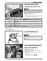
CDI UNIT INSPECTION
CDI IGNITION CIRCUIT INSPECTION
PULSE GENERATOR INSPECTION
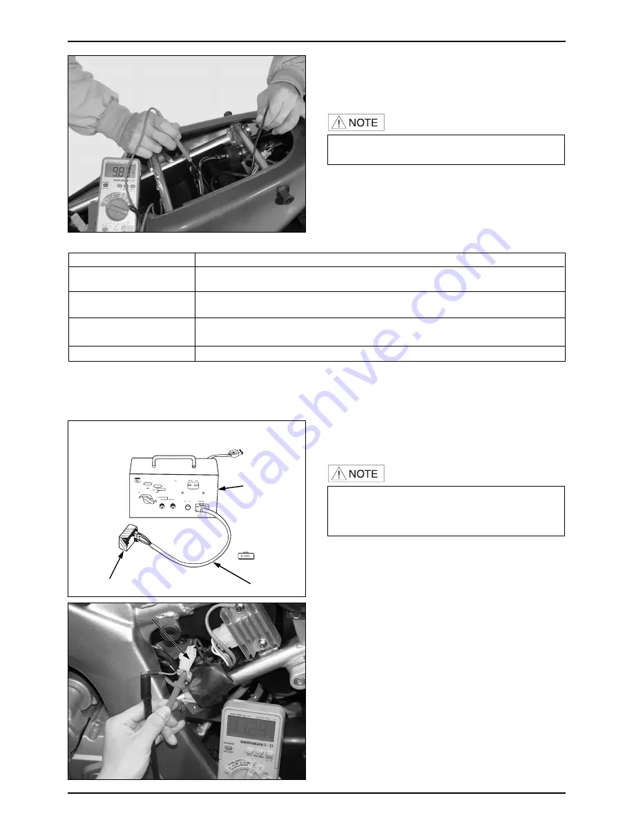
RESISTANCE MEASUREMENT
●
Remove the seat. (
⇨
12-2
)
●
Remove the LH. side cover (
⇨
12-2
)
●
Disconnect the A. C. generator 4P coupler and
blue/yellow wire connector.
●
Measure the resistance between the green and
blue/yellow.
STANDARD VALUE : 90~150
Ω
Ω
(20
℃
℃
)
CDI UNIT PERFORMANCE TEST
●
The CDI unit is checked by the CDI tester.
●
Remove the seat. (
⇨
12-2
)
●
Remove the rear seat. (
⇨
12-2
)
●
Disconnect the CDI unit coupler and check the ignition
system circuits from the wire harness side.
●
If there are a normality in the diagonosis above, and if there is no spark at plug, check the CDI unit and ignition coil by
using a CDI tester.
TOOL : DIGITAL TESTER
Inspection Items
ITEM
GROUND WIRE
IGNITION COIL (PRIMARY COIL)
PULSE GENERATOR
MAIN SWITCH
Check that there is battery voltage between main switch wire (black) and ground wire when the
ignition is ON
Check that the resistance of coil (between blue / yellow and green) is within the specified range.
( 90~150
Ω,
20
℃
)
Check that the resistance of coil (between black / yellow and green) is within the specified range.
( 0.1~0.3
Ω,
20
℃
)
Check continuity between ground and frame.
INSPECTION
A.C. GENERATOR COUPLER
A.C. GENERATOR COUPLER
A.C. GENERATOR COUPLER
A.C. GENERATOR COUPLER
A.C. GENERATOR COUPLER
A.C. GENERATOR COUPLER
A.C. GENERATOR COUPLER
A.C. GENERATOR COUPLER
A.C. GENERATOR COUPLER
A.C. GENERATOR COUPLER
A.C. GENERATOR COUPLER
A.C. GENERATOR COUPLER
A.C. GENERATOR COUPLER
A.C. GENERATOR COUPLER
A.C. GENERATOR COUPLER
A.C. GENERATOR COUPLER
CDI TESTER
CDI UNIT
INSPECTION ADAPTOR
Summary of Contents for ROADWIN VJ125 - SERVICE
Page 3: ......
Page 23: ...MEMO...
Page 39: ...MEMO...
Page 47: ...4 0 FUEL SYSTEM...
Page 60: ...MEMO...
Page 61: ...5 0 COOLING SYSTEM...
Page 64: ...MEMO...
Page 65: ...6 0 ENGINE REMOVAL INSTALLATION...
Page 69: ...7 0 CLUTCH GEARSHIFT...
Page 82: ...MEMO...
Page 83: ...8 0 A C GENERATOR STARTER CLUTCH...
Page 93: ...9 0 CYLINDER HEAD VALVES...
Page 109: ...10 0 CYLINDER PISTON...
Page 116: ...MEMO...
Page 117: ...11 0 CRANKCASE TRANSMISSION CRANKSHAFT...
Page 130: ...MEMO...
Page 131: ...12 0 EXTERNAL PARTS...
Page 137: ...13 0 FRONT WHEEL FRONT FORK STEERING...
Page 161: ...14 0 REAR WHEEL REAR SUSPENSION...
Page 174: ...MEMO...
Page 175: ...15 0 HYDRAULIC BRAKE FRONT REAR...
Page 200: ...MEMO...
Page 208: ...MEMO...
Page 216: ...MEMO...
Page 228: ...MEMO...
Page 241: ...MEMO...
Page 249: ...MEMO...
Page 250: ...MEMO...
Page 251: ...SERVICEMANUAL 2004 1 PRINTED 2004 1 PUBLICATION NO C COPY...

