9-3
CYLINDER HEAD / VALVE
CAMSHAFT
REMOVAL
●
Remove the luggage box.
(
⇨
3-2 )
●
Remove the center cover.
(
⇨
3-3 )
●
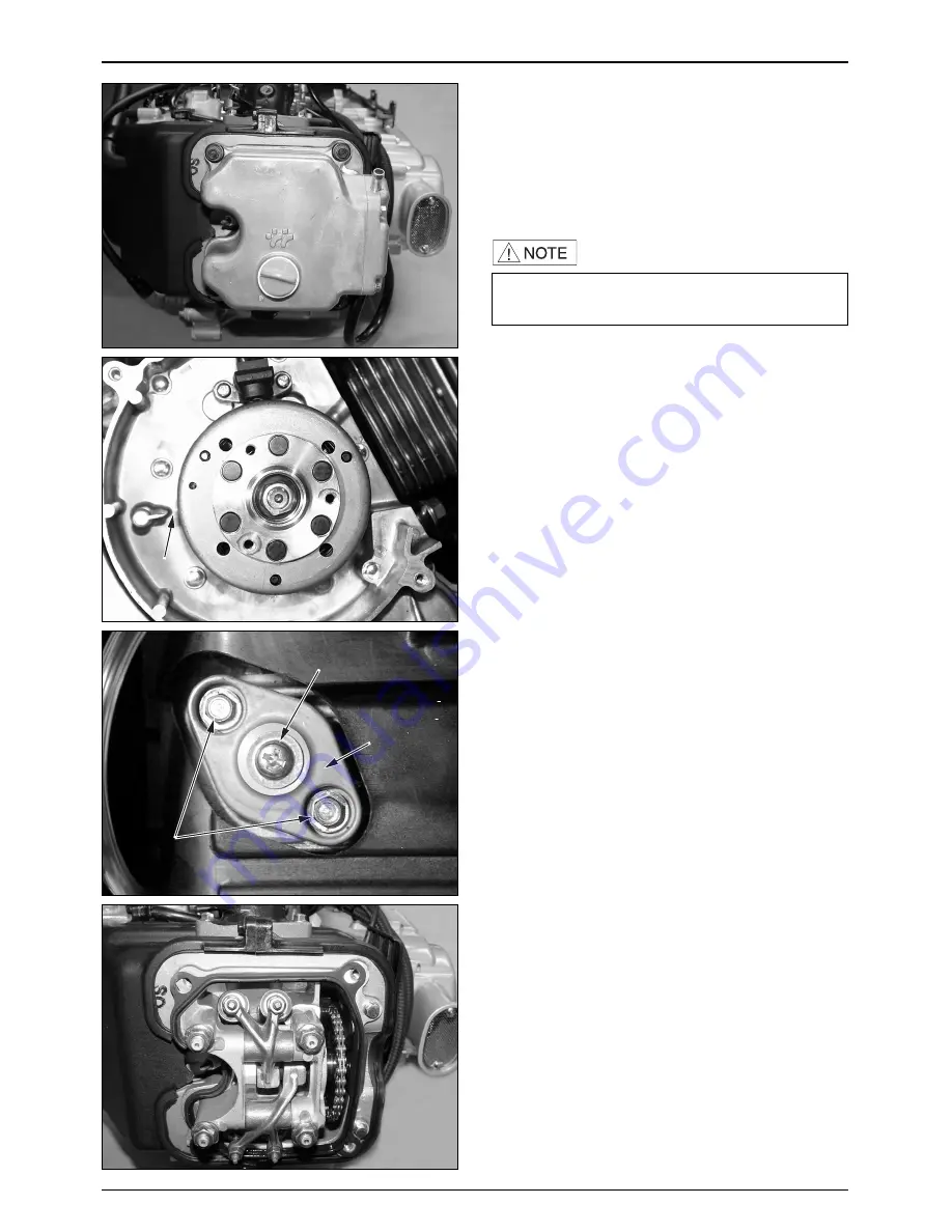
Loosen the cylinder head cover bolts, remove the cover.
●
Remove the shroud grommet B of the fan cover.
●
Turn the crankshaft to the left, and align the
“
T
”
mark
of the flywheel with the index mark of the RH.
crankcase cover.
●
Verify that the piston is located at the top dead center.
(Make all camshaft lobes face downward.)
●
If all camshaft lobes face upward, rotate the crankshaft
to the left for 1 turn (360
°
), and align the
“
T
”
mark
with the index mark once again.
●
Loosen the pan screw of the cam chain, remove the
tensioner flange bolts and tensioner lifter.
●
Loosen the 4 camshaft holder 8mm nuts.
●
Remove the cam cover plate.
●
Remove the camshaft holder from the cylinder head.
·
The camshaft can be maintained without
removing the engine.
"T" MARK
PAN SCREW
CAM CHAIN
TENSIONER
LIFTER
FLANGE BOLT
Summary of Contents for S2 125
Page 1: ......
Page 3: ......
Page 21: ...MEMO...
Page 49: ...MEMO...
Page 59: ...MEMO...
Page 63: ...7 0 LH CRANKCASECOVER CONTINUOUSLYVARIABLE TRANSMISSION LH CRANKCASE COVER...
Page 77: ...8 0 A C GENERATOR STARTER CLUTCH FLYWHEEL STATOR COMP RH SHROUD COOLING FAN...
Page 86: ...MEMO...
Page 103: ...10 0 CYLINDER PISTON CYLINDER CYLINDER GASKET PISTON TOP RING SECOND RING OIL RING...
Page 110: ...MEMO...
Page 111: ...11 0 TRANSMISSION CRANKSHAFT CRANKCASE RH CRANKCASE LH CRANKCASE CRANKSHAFT...
Page 122: ...MEMO...
Page 144: ...MEMO...
Page 145: ...13 0 REAR WHEEL BRAKE SUSPENSION REAR SWING ARM...
Page 154: ...MEMO...
Page 168: ...MEMO...
Page 177: ...MEMO...
Page 183: ...SERVICEMANUAL 2004 11 PRINTED 2004 11 PUBLICATION NO COPY...


