background image

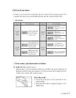
6) Code 33 (System error)

-   This error indicates the inner controller is damaged seriously.
- Please call your local representative.

7) Code 41 (Power supply error)

-   Code 41 is displayed if the power supply from the outer AC power generates any 

problem.

- Please call your local representative.

8) Code 42

-   Code 42 is displayed when there is a problem with the power supply generated by the 

inner batteries. Please call your local representative.

3.3  System description

(1) Main compositions

1) DVT-2600 controller

 Voltage and AC power 

   :   100-200V~, 50/60Hz

 Power consumption : 25W(35VA)

 Output : 2

 Pressure range 

   :   LEG - 20~60mmHg 

Foot - 120~140mmHg

DS MAREF

 13

Summary of Contents for DVT-2600

Page 1: ...efully This manual is for user s safety and preventing any property loss Before using our device please read this manual inevitably www dsmaref com The Venous Assist System User Manual This product is medical device using under doctor s instructions ...

Page 2: ...d until the stop button is activated The DVT 2600 has an integrated self checking system which includes checks for the digital sensor cuff connection and power supply If an error code shows during initial operation of the DVT 2600 it can be checked against the error code key attached to the side of the DVT 2600 unit for convenient reference 2 1 Contraindications The DVT 2600 system is not recommen...

Page 3: ...f a medical practitioner Do not attempt to repair a faulty device or replace broken tubing connectors as abnormal inflation of the cuff may occur Contact your local representative Use the device with a suitable AC power cord observing the electronic standards for each local region Fire and electric shock are possible 2 4 Clause 5 1 Type of protection against electric shock Class I equipment 2 Degr...

Page 4: ...rient or relocate the receiving device Increase the separation between the equipment Connect the equipment into an outlet on a different circuit from that to which the other device s are connected Consult the manufacturer or field service technician for help 2 6 WEEE marking This marking shown on the product or its literature indicates that it should not be disposed of with other household waste a...

Page 5: ... to help with the treatment of DVT by accelerating blood circulation in the lower limbs Please use this product in accordance with medical direction How to connect the hose to the cuff The controller has a self test function to automatically recognise the kind of cuff s connected to it during initial operation Press the START STOP button after turning on the power switch to initiate this self test...

Page 6: ... cuff connected LEG CALF BOOT CUFF 40mmHg This value is not able to be changed during operation Basic pressure is set at 40mmHg This pressure setting can be changed at 10mmHg increments ex 40 50 60 20 30 40mmHg The LCD screen will remain turned off if the user does not apply the cuff as the controller automatically selects the cuff when the START STOP button is selected 6 DVT 2600 ...

Page 7: ... STOP button is selected The controller has an automatic gradient pressure application which applies gradient pressure into each chamber of a cuff sequentially 5mmHg For cuffs with 3 chambers such as the leg calf boot cuff if 40mmHg is set pressure will be delivered as 35 40 45mmHg to the three chambers 3 Interval Button This button sets the interval time The time value which the user sets will be...

Page 8: ...ower indicator AC power indicator LED represents one of power input or the fail of power input 3 Battery charging indicator Indicates whether batteries are charging Indication of the battery charge level will not be displayed when the unit is off The indicator for battery charging will be displayed only when the batteries are not fully charged The batteries require the device to be powered on for ...

Page 9: ...ing condition and the type of applied cuffs Initial self test will detect the type of cuff When the device is turned on the controller will check the type of cuff During the controller check the symbols below will be gradually encircled demonstrating progress of the check The operation indicator below displays the variety of cuff types which may be used Please note if there is no cuff applied to t...

Page 10: ... start after pressurisation of both legs 3 Interval Mode After initial pressurisation the interval time setting on the LCD counter will decrease gradually and will restart the pressurisation cycle at the end of the interval time 2 Lymph Operating Mode In Lymph Mode the controller first pressurizes the cuffs Refer to picture 2 The Interval time will start after pressurisation of both legs Foot cuff...

Page 11: ...ller will revert back to Waiting Mode when the user presses START STOP Error Mode Segment Error 10 Cuff connection error This error mark will be on the screen if there is no cuff connection to the controller Lower pressure error Under the 30 pressure has consecutively checked five times Vent error Pressure in cuff doesn t ventilate Pump error When the device pump has an error Device error When the...

Page 12: ...n 30 of the set value are detected more than 3 times during operation it will indicate Error code 22 Checking points Check whether the hose is bent Check if there is something blocking the hose Check whether air socket is blocked 4 Code 31 Ventilation error If air is not ventilated deflated under 20mmHg during INTERVAL TIME Error code 31 will be indicated Checking points Check the inner solenoid v...

Page 13: ...C power generates any problem Please call your local representative 8 Code 42 Code 42 is displayed when there is a problem with the power supply generated by the inner batteries Please call your local representative 3 3 System description 1 Main compositions 1 DVT 2600 controller Voltage and AC power 100 200V 50 60Hz Power consumption 25W 35VA Output 2 Pressure range LEG 20 60mmHg Foot 120 140mmHg...

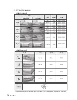
Page 14: ...e size One size 80cm 66cm 42cm 63cm DS111 DS121 DS131 DS141 60cm 75cm 93cm 113cm 50cm 62cm 77cm 97cm 42cm 63cm DS011 DS211 DS012 DS212 DS013 DS213 DS014 DS214 DS021 DS221 DS022 DS222 DS023 DS223 DS024 DS224 DS031 DS231 DS041 DS241 Thigh cuff Thigh cuff Calf cuff Calf cuff Foot cuff Foot cuff Boot cuff Boot cuff The dimensions given in the above table may deviate by 2 3cm depending on production co...

Page 15: ... after the cuffs are applied to the patient Turn the power on to the device after connecting the hoses to the air socket at rear of device to ensure self check 2 Do not operate with patient standing or sitting down There could be a risk of malfunction of the device and cuffs 3 The manufacturer recommends using basic pressure settings for initial use Caution is recommended for manual pressure setti...

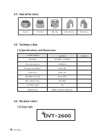
Page 16: ...ew Rear view Right side view Left side view Test descriptions Standard Remarks AC voltage Power consumption Air power consumption Noise level Operation nose level Max pressure level Controller weight Controller size 100 240V 50 60Hz 25W 35VA below 5W Above 2 KV below 60dB 140mmHg 2kg 200 W x 165 D x 190 H mm 16 DVT 2600 ...

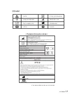
Page 17: ...n Europe certificate mark Service supplier mark LOT NO BF type medical equipment Manufacturer mark Production date Serial No Products information sticker This label is attached on the rear of a controller DS MAREF 17 ...

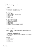
Page 18: ... A Thigh cuff large Medium Small B Calf cuff Large Medium small C Foot cuff One size D Boot cuff One size E Multi use cuff Thigh calf foot and boot One size 4 2 Product checking Caution Do not open the box with a sharp knife or scissors The product may be damaged 1 Composition inspection in a box Check the accessories included are correct as ordered and that a user manual is included in the box 1 ...

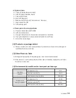
Page 19: ... E AC cord for local voltage 2 Products or package defect A Please contact your local representative if products are found to be damaged or quantities items are incorrect 3 Other Points to Note A Damage during opening of the package by a user cannot be warranted B Store device in a safe place protected from dust or humidity Unplug the unit when the device is not in use 4 Environmental conditions f...

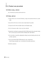
Page 20: ...with the connectable hose s 4 Turn on the power switch at the rear of the controller 5 Operate the controller by pressing the START STOP button for the automatic setting DVT or enter pressure and interval time manually after initial inflation 6 The controller will operate automatically utilizing the entered settings after the cuff self test operation 7 Press and hold the START STOP button for 3 se...

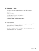
Page 21: ...e of device 5 Temporary numbness or Irritation caused by the cuff 5 4 Setting and use As DVT 2600 is a medical device for the purpose of assisting with venous therapy DVT 2600 is to be used only under medical supervision The device is not recommended for long term use Over time the patient may become accustomed to the compression pressures and hence benefits from use of the device diminish DS MARE...

Page 22: ... Keep the device in a clean place and protect from dust Cuff Disposable cuffs are for single use by one person only Keep cuffs or hose away from water or dust Do not blow air into the cuff while it is not fitted securely to the body Damage anti endurance risk Do not keep cuffs near sharps Battery Avoid dropping or shocking Prevent from being soaked in liquid Do not touch any material leaking from ...

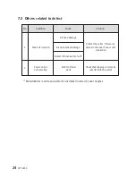
Page 23: ...condition Hose connection error or bent hose Check that the plug is correctly inserted into the power outlet Turn power to the controller off and on Check that the plug is correctly inserted into the outlet Check that the device is installed horizontally Check that there is nothing laying on top of the device or underneath Check that the hose is inserted correctly into the device Check that the ho...

Page 24: ...ket damage Defect of Inner parts of cuff Defect of Inner parts Contact the seller if there is a defect in the inner hose or cuff connection Check that the plug is correctly inserted into the outlet No Condition Solution Cause Manufacturer is not responsible for any defect incurred by user neglect 24 DVT 2600 ...

Page 25: ... 2EA MAIN_BOARD_LCD 1EA WINDOW_SHEET 1EA No Name 2 1 2 2 2 3 2 4 2 5 2 6 2 7 2 8 2 9 2 10 2 11 2 12 2 13 2 14 FRAME_MAIN 1EA SHEET_PLATE 1EA COVER_PLUG 2EA RUBBER_HOSE_ELBOW 6EA SOLENOID 2EA RUBBER_HOSE_CONNECTOR 1EA RUBBER_HOSE_PRESSURE 70mm M3XL5S 8EA PUMP 1EA SPONGE 3EA RUBBER_VIBRATION 2EA M4XL10 TP 2EA RUBBER_HOSE 120mm RUBBER_HOSE 20mm No Name 8 Schematics DS MAREF 25 ...

Page 26: ...ME SUB_ASM_REAR SMPS 1EA M3XL5 S 2EA M3XL8 TT 8EA BATTERY 1EA CAB_BATTERY 1EA M3XL4 M 1EA RUBBER_FOOT 4EA STICKER ERROR_CODE 1EA LABEL 1EA STICKER WARNING 1EA STICKER LEFT 1EA STICKER RIGHT 1EA No Name 3 Parts Assembly Diagram SUB ASM REAR 3 1 3 2 3 3 3 4 REAR_COVER 1EA RUBBER_PAD 2EA SUB_BOARD_CHARGE 1EA AC_INLET 1EA No Name 26 DVT 2600 ...

Page 27: ... by the user or any of the following 1 Malfunction caused by strong impact 2 Unauthorised repair or parts 3 Use of the device in a prohibited place 4 Not following the user manual 5 Cuffs are articles of consumption and are not under warranty Warranty DESCRIPTION MODEL NAME SERIAL NO WARRANTY BUYING PLACE BUYING DATE The Venous Assist System DVT 2600 Controller 2 years ...

Page 28: ...orld class products award 2004 Vice president award 2004 SFDA in China 2003 Success Design product 2003 FDA in USA 2002 ISO9001 EN13485 2002 CE marks DL series MK series DL1200 DVT 2600 1986 DS MAREF is established History Certificates 689 31 Geumjung dong Gunpo shi Geonggi do 435 862 Korea Tel 82 31 459 7211 Fax 82 31 459 7215 E mail ds dsmaref com http www dsmaref com 18 Chemin Des Courses 31100...

Reviews: