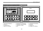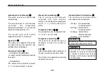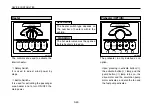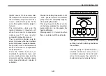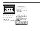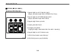
Upon activation of the number
⑤
automatic switch, the A/C operates
until it reaches the set temperature,
and the A/C compressor switch lamp
turns on. The unloading valve
operates until the set temperature -2
℃
is reached, and the compressor is
only 50
%
operated.
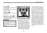
Upon activation of the number
⑥
A/C
compressor activation switch, the
compressor clutch turns
“
ON
”
and
the A/C activates.
The numbers
⑦
,
⑧
, and
⑨
fan power
control switches are used to
manually select low, mid, and high
speed operations of the A/C.
Activation of theses switches during
automatic operation shifts the system
to manual operation.
The number
⑩
warning indicator lamp
turns on when a fault is detected in the
pressure of the A/C compressor, and
the warning buzzer activates twice in
intervals of 5 seconds.
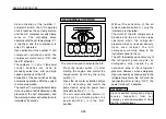
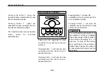
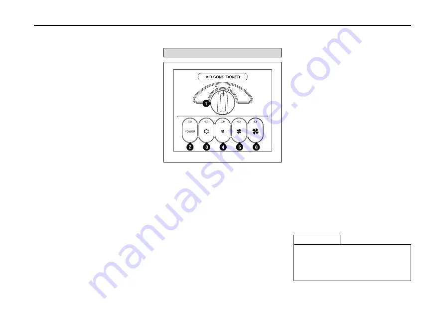
The control is used to activate the A/C.
Press the power switch (
②
) after
starting the engine, and control the
temperature by turning the rotary
switch (
①
).
Press the air cooler activation button
(
③
) for air cooling, and control the
power levels using the power level
activation buttons (
④
,
⑤
,
⑥
).
The air cooler activation button (
③
)
can only be activated when the
power switch(
②
) is in the
“
ON
”
position.
Without the activation of the air
cooler activation button(
③
), only the
internal air is circulated.
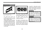
The clutch of the A/C compressor is
blocked and the air cooler stops
operation when the refrigerant
pressure drops or rises excessively.
Upon such incident, the A/C
emergency warning lamp in the
instrument panel turns on.
The A/C reactivates upon recovery of
the refrigerant pressure after an
emergency stop caused by an
excessive drop in the refrigerant
pressure. However, when emergency
stop is caused by excessive rise in the
refrigerant pressure, the A/C must be
reactivated after turning
“
OFF
”
the
power for about 10 minutes.
3-58
DEVICE CONTROL TIPS
Air Conditioner (OPTION)
OM-B448
REFERENCE
Upon repetitive emergency stops,
receive inspection from our
company
’
s service providers of from
the A/C manufacturer.
·
·
·
·
·
·
·
·
·
Summary of Contents for BS Series
Page 1: ......
Page 13: ...DEALER IMPRINT...
Page 153: ...6 11 VEHICLE INSPECTION AND MAINTENANCE OM F115E TYPE B...
Page 260: ......

