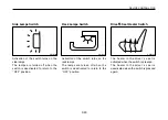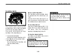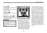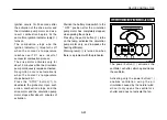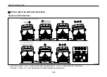
The controls are used to activate the
heater for the driver
’
s seat.
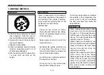
The upper lever controls the
activation and the power of the
heater. Pushing the lever to the right
results in increase of power.
The lower lever controls the direction
of the heater. Positioning the lever to
the further left controls the heater to
activate in the lower parts of the
driver
’
s seat and the windshield,
while positioning it to the further right
controls the heater to activate only in
the windshield.
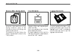
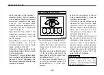
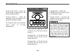
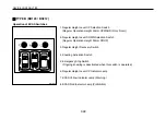
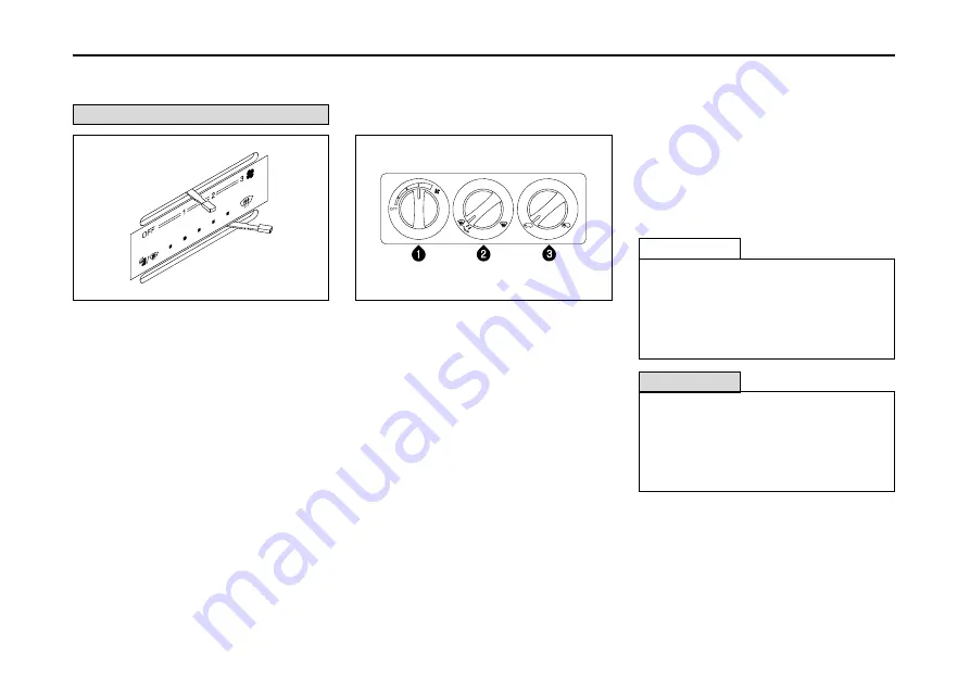
The number
①
rotary switch is used
for the activation/desctivation of the
driver seat heater and the control of
fan speed. Turning the switch
clockwise activates the system and
increases the fan power.
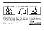
The number
②
rotary switch is used to
shift fan directions. Turning the switch
counterclockwise directs the fan
toward the front and lower section of
the driver, and turning it clockwise
dorects the fan towards the windshield.
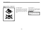
The number
③
rotary switch is used to
shift the source of the fan. Turning the
switch counterclockwise allows air from
outside, and turning it clockwise
circulates the air within.
3-59
DEVICE CONTROL TIPS
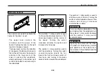
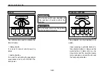
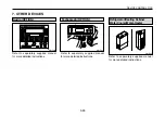
Defroster Controls
OM-S019
TYPE A
OM-H226
TYPE B
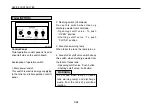
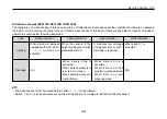
REFERENCE
For more effective elimination of frost
and moisture from the windshield, turn
the number
②
rotary switch clockwise
and the number
③
rotary switch
counterclockwise.
WARNING
Operating the vehicle with the inflow
of outside air blocked may disturb
safe operation of the vehicle due to
the moisture in the windshield and the
impure internal air.
·
·
Summary of Contents for BS Series
Page 1: ......
Page 13: ...DEALER IMPRINT...
Page 153: ...6 11 VEHICLE INSPECTION AND MAINTENANCE OM F115E TYPE B...
Page 260: ......

