13
TROUBLESHOOTING
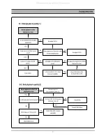
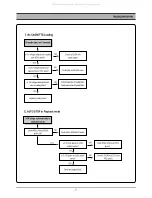
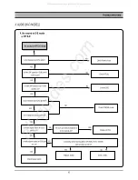
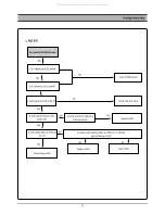
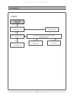
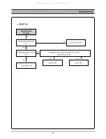
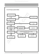
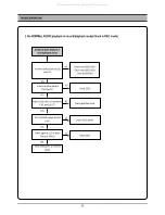
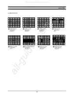
Is +5V supplied at IC301 pin#91?
NO
NO
YES
YES
Is VIDEO SW Pulse input at IC301
pin#70?
Is REC signal output from IC301
pin#94,95,89,90?
LP MODE: 89,90 Pin
SP MODE: 94,95Pin
Check video HEAD and Connector.
Is signal input into IC301
pin# 48,50,52,54,56?
Check POWER circuit.
Check IC501 pin#18.
Record video signal poor.
Check EE MODE.
YES
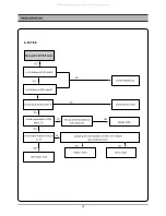
Is luminance and color signal
output from IC301 pin#78?
Replace IC301.
NO
NO
YES
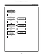
C. No recording
YES
Is IC301 pin#80 REC(H) HIGH?
Check IC501 pin#45.
NO
All manuals and user guides at all-guides.com
Summary of Contents for DC-G84D1D
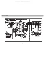
Page 29: ...28 CIRCUIT DIAGRAM 3 A V CIRCUIT DIAGRAM All manuals and user guides at all guides com...
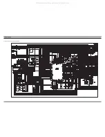
Page 37: ...36 PCB CIRCUIT BOARD 1 1 VCR MAIN All manuals and user guides at all guides com...
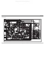
Page 38: ...37 PCB CIRCUIT BOARD 1 2 POWER All manuals and user guides at all guides com...
Page 39: ...38 PCB CIRCUIT BOARD 1 3 DVD MAIN All manuals and user guides at all guides com...
Page 45: ...44 INSTRUMENT DISASSEMBLY G Explode view All manuals and user guides at all guides com...


