background image

7                                                                                                Ver1.0 

II. Troubleshooting 


Adjust the power supply to 4.2V and make sure that power polarities are correct before 
plugging into the power to avoid the damage to PCBA.                                                                                 


1. Repair instruments:                                                                                                                     

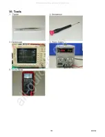
Tri-use meter, oscilloscope, power supply.


2. Troubleshooting:   


  Symptom                                                Repairing                                                           

(1). Press the power button and the power is not on: 

A.   Check to see if the SW1 function is normal. 
B.   Make sure that the U18.1 is at High, if U18.1 stays at Low check the 

following circuit. 

‹

  Check if the Q1.D voltage is normal first (2.2V~3.2V). 

      Replace the main board if no voltage on Q1.D. 

C.   If the U18.1 signal is normal, then use the meter to check if the 2.5V, 1.8V 

and 3.3V voltages are normal. Press down SW1 first and use tri-use meter to 
measure the following voltages. 

‹

   Remove U9, R34 and R36 first and then measure 2.5V to see if it is 

normal. 

    If U18 voltage is normal, replace the main board. 

‹

  If the 2.5V is normal, then check if the 1.8V voltage is normal. 

If it is not, replace the main board. 

‹

   Check if the 1.8V voltage is normal first and then check if the 3.3V 

voltage is normal. 

Make sure that the U8.2 output is at 3.7V first, if not, replace the main 
board. 

(2). Unable to turn the power on after opening the cover:


A.  While unable to turn the power on by opening the cover, use SW1 button to 

turn the power on first and make sure the power supply is normal. 

B. When the power is turned on by pressing SW1, check the circuit of cover 

opening. Check if the SW2.1 has voltage first, if not, check D18 and D4. If 
the voltage is normal, then check to see if when the magnet is nearing and 
away from SW2.2 its status changes from Low to High, if not, replace the 
main board. 

Unable to turn 
on the power 
 

(3). When plug in USB or Adaptor the power can not be turned on:     

A.  Turn the power on by pressing SW1 first to make sure that the power-on 

circuit is normal. Then check if the USB power-on circuit is normal. 

B.  Check if D11.1 has voltage first, if no voltage, check L9 and D17. 
C.  Measure to see if D14.2 has 4.3V voltage, if no voltage, replace the main 

board. 

D.  After making sure the input voltages are normal, check power-on circuit to 

make sure if Q1.D voltage is normal. If it is normal, check R26,C52,R51 
and D8 for any damages, or replace the main board. 

Power down 
after turning on 
 

(1). Press power button the red light is on and then power goes off: 

A.   Use oscilloscope to check if R17 had clock output first. 
B.  If the clock is not normal, it indicates that the program is not yet boot-up. 

Check to see if the circuit around U4 DDR RAM is normal. If normal then 
replace the main board. 

All manuals and user guides at all-guides.com

Summary of Contents for DMP-2000

Page 1: ...layer Model DMP 2000 S M No OSMP200001 May 2005 Caution In this Manual some parts can be changed for improving their performance without notice in the parts list All manuals and user guides at all gui...

Page 2: ...n after power on 6 z Abnormal LCD display 7 z Abnormal video 7 z Abnormal flashing 7 z Unable to charge battery 8 z Abnormal voice recording and replaying 8 z Inaccurate date and time 8 z Button press...

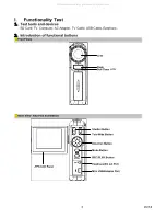
Page 3: ...able Earphone 2 Introduction of functional buttons Front View Rear View Key Pad Illustration Flash Mini USB Adaptor Port Earphone AV out Port REC PLAY Button Mode Button Direction Button Tele Wide But...

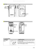
Page 4: ...y and press Power Button watch if the LCD normal B Press Power Button to turn off the power and close the LCD Panel and then open the LCD Panel to see if the LCD Panel display is normal Speaker Strap...

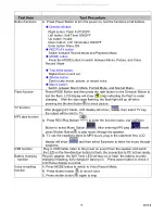
Page 5: ...ton to shoot picture TV function After plugging AV Cable LCD display will show then select TV key the output will be sent to TV MP3 play function A Press REC Play Button to enter the function manu use...

Page 6: ...ton When a film is under recording a time indicator will display on LCD monitor To stop recording press shutter button again B To view recorded films press the REC PLAY button once to switch to Playba...

Page 7: ...unable to turn the power on by opening the cover use SW1 button to turn the power on first and make sure the power supply is normal B When the power is turned on by pressing SW1 check the circuit of...

Page 8: ...ows white display due to bad LCD cable contact A Check if J2 Pin22 LCD_SCL Pin23 LCD_SDA and Pin24 LCD_CS have signal output B If the signals from LCD_CS LCD_SCL and LCD_SDA are normal then reinstall...

Page 9: ...rd 1 No sound after power on A Check if the soldering wire of U10 Speaker is broken B Replace U10 Speaker C If problem still remains after replacing the speaker replace the main board Abnormal sound r...

Page 10: ...10 Ver1 0 III Software Updating 1 Test devices Camera SD card battery or charger All manuals and user guides at all guides com...

Page 11: ...ing please check if the file on the SD card is correct E When LED is flashing please make sure the camera will not lose the power otherwise it will be failed when recording onto FW F Wait till the LED...

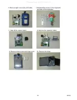
Page 12: ...LCD Cable 6 Disassemble screws on the keyboard and take off the keyboard 7 Take off the sensor board 8 Remove the capacitor holder 9 Remove hinge screw and hinge cover 10 Remove the hinge All manuals...

Page 13: ...A02 1 5 Left Cover 604 04220 A04 1 6 Right Cover 608 64220 A21 1 7 Battery Cover 608 64220 A22 1 8 Front Cover Assembly 618 04220 A04 1 9 LCD Panel 087 04220 A01 1 10 Capacitor Holder 608 14220 A04 1...

Page 14: ...14 Ver1 0 1 Main Board Assembly 2 Sensor Board Assembly 3 Key Board Assembly 4 LCD Board 5 Left Cover 6 Right Cover 7 Battery Cover 8 Front Cover Assembly All manuals and user guides at all guides com...

Page 15: ...l 10 Capacitor Holder 11 Speaker Holder 12 LCD Panel Front Cover Assembly 13 LCD Panel Rear Cover Assembly 14 Hinge Cable 15 Key PAD Assembly 16 Hinge Upper and Lower Covers All manuals and user guide...

Page 16: ...16 Ver1 0 VI Tools 1 Twister 2 Screwdriver 3 Oscilloscope 4 Power Supply 5 Tri use Meter All manuals and user guides at all guides com a l l g u i d e s c o m...

Reviews: