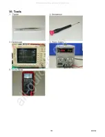
9 Ver1.0
(1). Unable to charge:
A. Check if the battery still has voltage, use tri-use meter to measure if the
U12.3 voltage is at High.
B. If the U12.3 voltage is at High, please check if the voltage is at 2.5V. If the
voltage is not accurate, check if R27 and R100 are normal.
C. If T1.5 does not have output voltage, then replace the main board.
D. If T1.5 voltage is normal then check if D10.1 has the output voltage. If the
output voltage is normal, replace C7.
Flash light not
normal
(2). No flash light:
A. Check if the discharge loop of the flash light circuit and the flash light bulb
are normal first.
B. Check if the D3.K signal is at High.
C. If D3.K signal is at High, then replace Q3. Otherwise check if D3.Ais at
High. If D3.A is at Low, then replace the main board.
D. If problem still remains after replacing SCR, replace the main board.
Symptom Repairing
Unable to charge
the battery
(1).Unable to charge the battery:
A. Check if J3.4 has 5V voltage first.
B. Check if R7 and R13 have the voltage greater than 2.0V.
C. Check if Q4.S has voltage, if not, replace the main board.
D. Check if Q4.D has voltage, if not, replace the main board.
E.
Check if D9.K has voltage, if not, replace the main board.
(1).No sound after power on:
A. Check if the soldering wire of U10 Speaker is broken.
B. Replace U10 Speaker.
C. If problem still remains after replacing the speaker, replace the main board.
Abnormal sound
recording and
replaying
(2). No sound or unclear sound while recording or replaying video:
A. Check if the connection between sensor board and main board is normal.
B. Check if C23, C24, R59 and R71 are normal.
C.
Replace U7 microphone.
D.
If problem remains after replacing the microphone, replace the main board.
Inaccurate date
and time
(1). Inaccurate date and time:
A. If the date and time is inaccurate after Power OFF and Power ON, check
R12 and C35.
B.
If date and time is too fast, check Y2.
C.
If problem still remains, replace the main board.
Button
malfunction
(1). Button malfunction after pressing:
A. Check if the connection between the key board and the main board is
normal.
B. If it is the five-direction button, please check if key board J1.10 shows the
following voltages when pressing different buttons: Enter (2.76V),
UP(2.20V), Down(1.65V), Left(1.12V), Right(0.55V). If not, check resistors
R1 - R6 or replace Dimple Dome. If J1.10 shows different voltages, please
check if main board J6.10 has the voltage variation. If not, replace the main
board.
C.
If other buttons shows problem, please check if Dimple Dome or board to
board connector is normal.
All manuals and user guides at all-guides.com


