7
Adjusting Method
Completion of control
- All adjustments need to be performed after for 1hour or more.
- Heat-run is executed in the state of non-signal noise.
- If a retrace line appears on the screen during heat-run, rotate the screen VR left and carry out
heat-run when it disappears.
- Note) If stop image is kept over 10 min, a fluorescent material of CRT can be damaged.
Step 1. Control of screen voltage
1) Press the S9 key of Service Remote Control when set’s on.
2) Select PICTURE OFF & VERTICAL OFF. After turning the screen VR of focus pack right,
slowly rotate it left when a horizontal line appears and fix it when the line disappears
completely.
3) Control Red VR, Green VR and Blue VR in the order.
4) Fix the VR by lock paint after the control is completed.
Note) This control should be performed in a darkroom.
Step 2. Control of P-Lens focus
1) Receive RETMA pattern.
2) Loose the fixing nut of lens.
3) Rotate the fixing nut of lens left and then right slowly. Fix the optimum focus position by
repeating this method.
Note 1) Control the focus on the basis of 6cm by 6cm (intra-office signal 8CH, No.3) at the
left bottom of the screen.
Note 2) Perform the focus readjustment or correction if the entire screen isn’t focused even
after the completion of focus control.
Applied chassis and model:SJ-113/DSJ-4710(20)
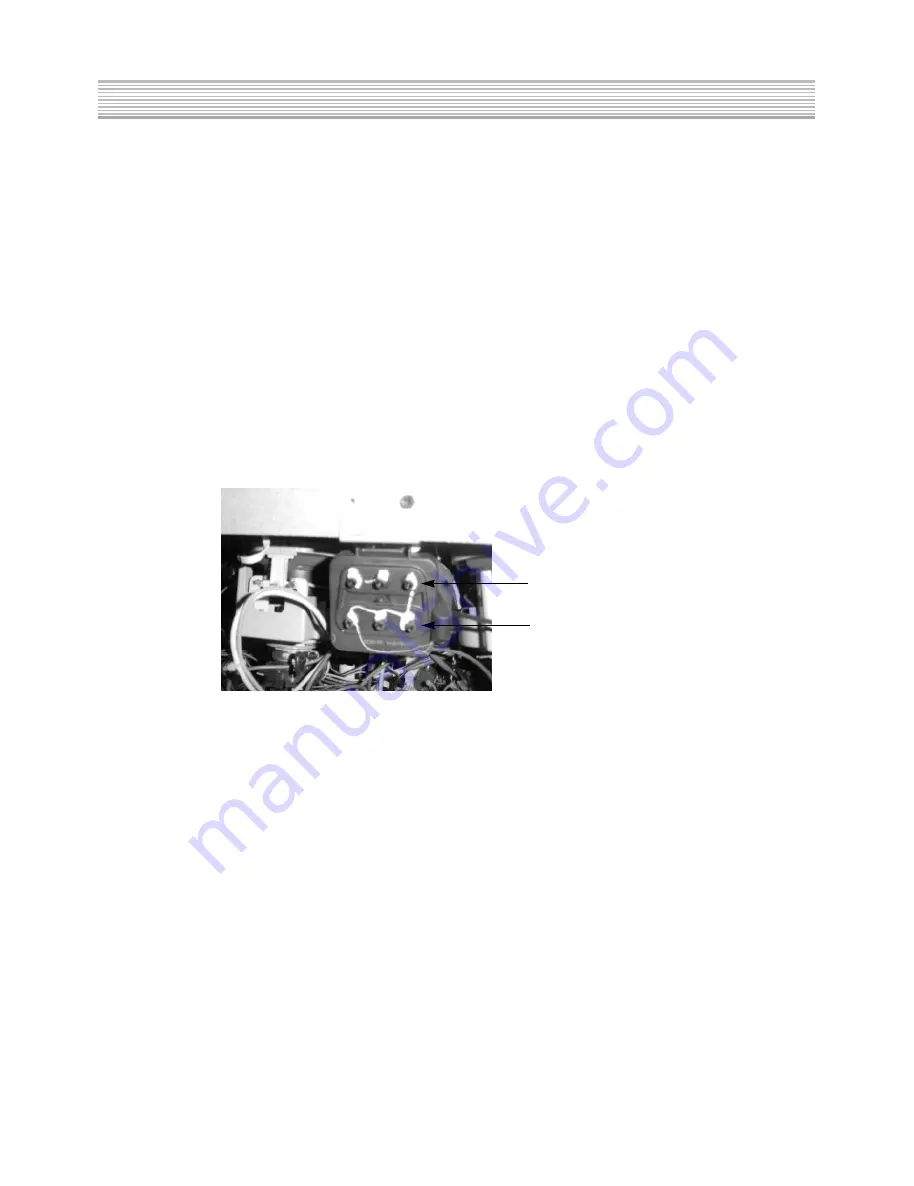
SCREEN(R/G/B)
FOCUS(R/G/B)
[Figure 2. Exterior view of focus-pack]
All manuals and user guides at all-guides.com
Summary of Contents for DSJ-4710CRU
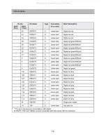
Page 14: ...13 IC Description All manuals and user guides at all guides com...
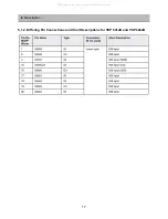
Page 15: ...14 IC Description All manuals and user guides at all guides com...
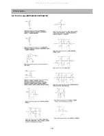
Page 16: ...15 IC Description All manuals and user guides at all guides com a l l g u i d e s c o m...
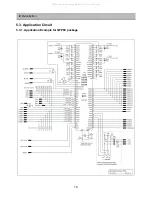
Page 17: ...16 IC Description All manuals and user guides at all guides com...
Page 22: ...21 IC Description All manuals and user guides at all guides com...
Page 23: ...22 IC Description All manuals and user guides at all guides com...
Page 24: ...23 IC Description All manuals and user guides at all guides com...
Page 25: ...24 IC Description All manuals and user guides at all guides com...
Page 26: ...25 IC Description All manuals and user guides at all guides com a l l g u i d e s c o m...
Page 27: ...26 IC Description All manuals and user guides at all guides com...
Page 28: ...27 IC Description All manuals and user guides at all guides com...
Page 29: ...28 IC Description All manuals and user guides at all guides com...
Page 30: ...29 IC Description All manuals and user guides at all guides com...
Page 52: ...51 8 Schematic Diagram 1 Block Diagram All manuals and user guides at all guides com...
Page 53: ...52 Schematic Diagram 2 Power All manuals and user guides at all guides com...
Page 54: ...53 Schematic Diagram 3 Convergence AMP All manuals and user guides at all guides com...
Page 55: ...54 Schematic Diagram 4 Convergence Module All manuals and user guides at all guides com...
Page 57: ...56 6 IF Module Schematic Diagram All manuals and user guides at all guides com...
Page 58: ...57 7 AV Main Schematic Diagram All manuals and user guides at all guides com...
Page 59: ...58 8 Micom Module Schematic Diagram All manuals and user guides at all guides com...
Page 60: ...59 9 Control Union Schematic Diagram All manuals and user guides at all guides com...
Page 62: ...61 2 Power PCB PRINTED CIRCUIT BOARD All manuals and user guides at all guides com...
Page 64: ...63 4 IF Module PCB PRINTED CIRCUIT BOARD All manuals and user guides at all guides com...
Page 65: ...64 5 CRT PCB PRINTED CIRCUIT BOARD All manuals and user guides at all guides com...
Page 67: ...66 1 DSJ 4710CRU 10 EXPLODED VIEW All manuals and user guides at all guides com...
Page 68: ...67 2 DSJ 4720CRU EXPLODED VIEW All manuals and user guides at all guides com...
Page 69: ...All manuals and user guides at all guides com...


