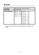
background image

8

MAIN MENU

MAIN MENU

HOW T

HOW T

O USE SUB MENUS

O USE SUB MENUS

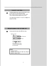
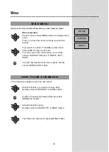
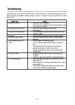
All menus are removed within 25 seconds if you don’t press any button.

The following is applied to all of the sub-menus.

Menus

Direct selection 
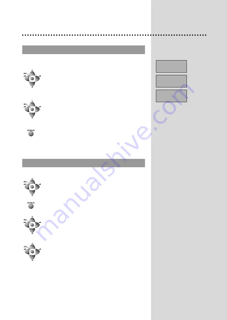
Press remote control MENU button to display main
menu.                                                          
Then, you have the choice among several sub-
menus.

If you want to cancel immediately main menu,
press MENU button once more.
To select one of the sub-menus, use remote
control CURSOR buttons UP, DOWN, LEFT,
RIGHT.

To enter the selected sub-menu, press remote 
control NORMAL/OK button .

Select the function you want to change using 
Remote control CURSOR UP or DOWN button.

Confirm (if needed) by pressing Remote control
NORMAL/OK button .

Adjust the function using
Remote control CURSOR LEFT or RIGHT button.

Then Return to main menu pressing MENU button .
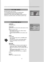
PICTURE

FEATURES

INSTALL

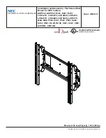
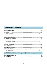
Summary of Contents for DTA-14V1

Page 1: ...14D2T 20D2T 21D2T 14D3 20D3 21D3 14D3T 20D3T 21D3T 14D4 20D4 21D4 14D4T 20D4T 21D4T 14D4TS 20D4TS 21D4TS 14D6T 20D6T 21D6T 14D7 20D7 21D7 14D7T 20D7T 21D7T 14D9 20D9 21D9 14D9T 20D9T 21D9T 21U6 21U6T...

Page 2: ...tents Important safeguards 1 Before Operation 2 Connecting external equipment 3 Identification of Controls 5 Daily use 6 Menus 8 Teletext Option 14 Quran function 15 Specifications 16 Troubleshooting...

Page 3: ...ver the ventilation openings in the cabinet and never place the set in a confined space such as a bookcase or built in unless proper ventilation is provided Leave a minimum 10cm gap all around the uni...

Page 4: ...lly connected to the set by means of 75 ohm SWITCHING ON AND OFF Switching on Switch the set on with the MAIN POWER button ON OFF and then PR UP button on the front of the set Or button or the PR UP b...

Page 5: ...een display will be changed as shown AV TV S VHS is Russia only This is used to connect a VCR a Camcorder a S VHS VCR a PERI TV decoder or a video game console In most cases the set changes automatica...

Page 6: ...V Audio Video socket with an appropriate cable to the corresponding socket of the external equipment Select AV mode by pressing the TV AV button Press the TV AV button to return to the TV mode HEADPHO...

Page 7: ...KIP DELETE MODE MENU NORMAL OK 1 2 3 4 5 6 7 8 0 9 1 2 3 5 6 7 8 9 4 10 11 13 14 16 18 17 15 12 VIDEO AUDIO POWER NUMBER0 9 NORMAL OK AV PR CURSOR UP VOLUMEUP CURSORRIGHT MENU PR CURSOR DOWN VOLUMEDOW...

Page 8: ...E Volume adjustment Use VOLUME UP DOWN buttons of the remote control unit or on the front of the set Mute Get sound off by pressing the remote control MUTE button Then logo is displayed Sound returns...

Page 9: ...OFF The set will be turned off after the time you set The remaining time before TV turn off is displayed on programme status Accessed by the Remote Control RECALL button Programme number Remaining tim...

Page 10: ...f you want to cancel immediately main menu press MENU button once more To select one of the sub menus use remote control CURSOR buttons UP DOWN LEFT RIGHT To enter the selected sub menu press remote c...

Page 11: ...lighted child lock is operating The set can only be switched ON with the remote control unit CLOCK TV clock setting Set TV clock with remote control 0 9 NUMBER buttons then clock starts Note that if y...

Page 12: ...T Programme list edition FREQ Channel Frequency NAME Channel name PROGRAM Programme number STORE TO Programme storage number PR Programme number NAME Station name Skip programme skipped INSTALL AUTO S...

Page 13: ...on screen when changing programmes with PR UP DOWN buttons Channel deleting Select the programme to delete using remote control CURSOR UP DOWN buttons Press the remote control DELETE button The delet...

Page 14: ...er of this programme are displayed in the install menu Channel searching Select FREQ function Press the remote the remote control CURSOR RIGHT LEFT buttons for more than 3 seconds to start up down man...

Page 15: ...also used if you want to copy a programme already memorized to another programme number You can call up the MENU without the remote control unit You can enter the MENU directly by pressing the MENU b...

Page 16: ...n the current subpage appear COLOUR BUTTONS IN TOP FLOF TELETEXT A red green yellow and cyan field is shown at the bottom of the screen If TOP or FLOF teletext FASTEXT is transmitted by the station pr...

Page 17: ...ess again to hide it VOLUME BRIGHTNESS CONTROL Repeatedly pressing the MENU button in teletext mode VOLUME or BRIGHTNESS appears at the bottom of the screen You can control it with the LEFT RIGHT butt...

Page 18: ...nt specifications may change TV Standard PAL SECAM B G H NTSC AV ONLY Main Voltage AC 240V 50Hz Power Consumption DTB 14 57W DTA 14V 49W DTB 16 64W DTA 14U 57W DTB 20 68W DTA 20V1 60W DTB 21 74W DTA 2...

Page 19: ...um position Excessive noise in picture Check the Antenna Cable is broken or disconnected or damaged Diagonal stripes appear on It may be affected by interfering signal picture ex from nearby amateur r...

Page 20: ...URO SCART Audio Video and Out R G B in slow and fast wtching SVHS in Audio Video jack on front of cabinet in common connection with EURO SCART Headphone jack 3 5mm on front of cabinet R 40A10 14 39W 2...

Page 21: ...3 1 21 Pin EURO SCART 3 2 Channel table 4 CIRCUIT BLOCK DIAGRAM 6 ALIGNMENT INSTRUCTIONS 7 1 Service mode 7 2 Microcontroller configuration 7 3 TV SET Alignment 7 SCHEMATIC DIAGRAM 9 EXPLODED VIEW 10...

Page 22: ...igh potential of the picture tube before handling the tube The picture tube is highly evacuated and if broken glass fragments will be violently expelled 2 If any Fuse in this TV receiver is blown repl...

Page 23: ...e 10k 7 Blue Input 0 7Vpp 0 1V Inpedance 75 8 Slow Switching TV 0 to 2V AV 4 5 to 12V Impedance 10k 9 Green Earth 10 N C 11 Green Input 0 7Vpp 0 1V Impedance 75 12 N C 13 Red Earth 14 Blanking Earth 1...

Page 24: ...25 591 25 591 25 591 25 C37 599 25 599 25 599 25 599 25 C38 607 25 607 25 607 25 607 25 C39 615 25 615 25 615 25 615 25 SPECIFICATIONS CH EUROP E CCIR FRANCE GB IRE LAND EAST OIRT C40 623 25 623 25 6...

Page 25: ...9 287 25 160 00 303 25 287 25 S20 294 25 294 25 S21 303 25 303 25 303 25 SPECIFICATIONS CH EUROP E CCIR FRANCE GB IRE LAND EAST OIRT S22 311 25 311 25 311 25 311 25 S23 319 25 319 25 319 25 319 25 S24...

Page 26: ...6 CIRCUIT BLOCK DIAGRAM...

Page 27: ...tion TV set Alignment 1 G2 alignment Set TV in NORMAL I mode TV in AV mode without video signal Black screen TV preset with WP Red WP Green and WP Blue equal to 32 TV preset with Black R Black G equal...

Page 28: ...lope to compensate for vertical distortion 5 Horizontal picture centering Adjust H Shift to have the picture in the center of the screen 7 AGC Adjust the antenna signal level to 68 dB V 2 for Daewoo t...

Page 29: ......

Page 30: ...10 EXPLODED VIEW 1 14V3...

Page 31: ...11 EXPLODED VIEW 2 20V3...

Page 32: ...12 EXPLODED VIEW 3 21V3...

Page 33: ...13 PRINTED CIRCUIT BOARD CIRCUIT DIAGRAM 6 SERVO SYSCON CEC CIRCUIT DIAGRAM T DECK...

Page 34: ...PU 0 33MF J C801 CL1JB3474K C LINE ACROSS AC250V 0 47MF U C SNDF SV I C805 CEYN2W151P C ELECTRO 450V LHS 150MF 25X40 2 C812 CH1AFE472M C CERA AC 4KV 4700PF M KX DE1610 2 I D707 DSML1216W LED SML1216W...

Page 35: ...C ELECTRO 50V RSS 47MF 6 3X11 TP LOC PART CODE PART NAME PART DESCRIPTION REMARK C412 CEXF2C339V C ELECTRO 160V RSS 3 3MF 8X16 TP C414 CMXM2A104J C MYLAR 100V 0 1MF J TP C417 CMXL2E104K C MYLAR 250V M...

Page 36: ...F 0 1MF Z C520 CCZB1H102K C CERA 50V B 1000PF K AXIAL C521 CCZB1H102K C CERA 50V B 1000PF K AXIAL LOC PART CODE PART NAME PART DESCRIPTION REMARK C523 CCZF1H103Z C CERA 50V F 0 01MF Z C529 CBZF1H104Z...

Page 37: ...5 OHM J LOC PART CODE PART NAME PART DESCRIPTION REMARK R401 RD 4Z272J R CARBON FILM 1 4 2 7K OHM J R404 RD 4Z399J R CARBON FILM 1 4 3 9 OHM J R420 RD AZ223J R CARBON FILM 1 6 22K OHM J R501 RD AZ101J...

Page 38: ...OHM J R829 RD AZ223J R CARBON FILM 1 6 22K OHM J LOC PART CODE PART NAME PART DESCRIPTION REMARK R830 RD AZ332J R CARBON FILM 1 6 3 3K OHM J R840 RD 4Z220J R CARBON FILM 1 4 22 OHM J R841 RD 2Z249J R...

Page 39: ...J 1 6 6 8K OHM J R575 R CARBON FILM 1 6 12K OHM J 1 6 10K OHM J 1 6 12K OHM J R801 POSISTOR ECPCC140M290 ECPCD7R0M290 ECPCD7R0M290 R823 R CARBON FILM 1 4 4 3K OHM J 1 4 3K OHM J 1 4 3K OHM J SCT1 SOC...

Page 40: ...DAEWOO ELECTRONICS CO LTD 686 AHYEON DONG MAPO GU SEOUL KOREA C P O BOX 8003 SEOUL KOREA TELEX DWELEC K28177 8 CABLE DAEWOOELEC E mail djkoo web dwe co kr TEL 82 2 360 7806 FAX 82 2 360 7877...

Page 41: ...r and AGC circuit The nominal frequency of the demodulator is tuned to the required frequency 5 5 6 0 6 5 MHz by means of a calibra tion circuit which uses the clock frequency of the microcontroller a...

Page 42: ...saturation occurring when signals with a high chroma to burst ratio are received The ACL circuit is designed such that it only reduces the chroma signal and not the burst signal This has the advantage...

Page 43: ...od the vertical deflection is placed in an overscan position so that the discharge is not visible on the screen 2 IF The TDA9361 TDA9381 has an alignment free IF PLL demodulator The fully integrated o...

Page 44: ...ont RCA video input The controlling software via I2C bus selects the signal source Video signal from tuner Pin 40 External video External SVHS from SCART The sound source switching is done in the vide...

Page 45: ...inking and sourcing is active which leads to steep slopes The levels are 0 and Vddp the supply voltage 3 3Volts High impedance This mode can be used for input only operation of the port Special port f...

Page 46: ...ins via resistors R350 and R351 The differential input voltage is compared with the output current through the deflection coils measured as voltage across R302 which provides internal feed back inform...

Page 47: ...smoothing the winding volt age which appears between pin 6 and pin 7 of the SMPS transformer As this winding voltage does not increase to the set voltage immediately after the control circuit starts...

Page 48: ...P volt age 20 5V Vin t Waveform of Vin pin voltage at start up TO PIN4 SM PS 2 3 1 5 GND R804 C850 OCP FB From PIN 6 SM PS FEEDBACK SOURCE R808 DRAIN DRIVE OSC Rg2 Rg1 Comp 2 Comp 1 C1 R1 STR F6653 1...

Page 49: ...STR F6653 internal resistance R1 So C1 voltage starts falling in accordance to the gradient regulated by the constant dis charging time of C1 and R1 So this means that the fixed time determined by C1...

Page 50: ...his circuit triggers the latch circuit when the frame temperature of STR F6653 IC exceeds 140 C overvoltage protection circuit OVP This circuit triggers the latch circuit when the Vin voltage exceeds...

Page 51: ...picture appears on screen I501 IC doesn t provide horizon tal drive voltage Then the microcontroller consults I702 EEPROM via I2C bus to know the last TV set mode normal run mode or stand by mode befo...

Page 52: ...I501 pin 60 If the DC supply voltage decreases below 3 V Q510 switches off immediately Q511 starts conducting pulling I501 pin 60 high At the same time it discharges the reset capacitor C501 Dischargi...

Page 53: ...810 is not conducting and no current flows from Q810 collector to the ground Therefore the power circuit diagram is the following one 9 2 1 2 power supply circuit diagram during TV set normal run I820...

Page 54: ...er supply line IC power supply delivery Remarks 124V 110V FBT FBT supplies 45V to I301 vertical IC FBT supplies 14V to I301 vertical IC FBT supplies 33V to the tuner FBT supplies 185V to I901 video am...

Page 55: ...hich are conducting In these conditions I801 delivers pulses on light mode and T801 produces voltages with reduced power As I810 is conducting current flows also from pin 16 SMPS transformer to I823 3...

Page 56: ...band delay line RGB control circuit with Continuous Cathode Calibration white point and black level off set adjustment so that the colour temperature of the dark and the bright parts of the screen ca...

Page 57: ...colour palette Globally selectable scan lines per row 9 10 13 16 and character matrix 12x10 12xl3 12x16 VxH Fringing Shadow selectable from N S E W direction Fringe colour selectable Meshing of defin...

Page 58: ...al time capture and decoding for WST Teletext in Hardware to enable optimised microprocessor throughput 10 pages stored On Chip lnventory of transmitted Teletext pages stored in the Transmitted Page T...

Page 59: ...19 IC DESCRIPTION APPENDIX...

Page 60: ...ESCRIPTION n u 1 Port 1 3 Not used SCL 2 I2C bus clock line SDA 3 I2C Data line SECAM L out 4 Port 2 0 FM sound PushPull Low AM SECAM L PushPull High AM SECAM L High Impedance OCP 5 Port 3 0 Over Curr...

Page 61: ...sor CVBS Y 42 external CVBS Y input CHROMA 43 chrominance input SVHS AUDOUT 44 audio out INSSW2 45 2nd RGB insertion input R2IN 46 2nd R input G2IN 47 2nd G input B2IN 48 2nd B input BCLIN 49 beam cur...

Page 62: ...22 APPENDIX IC DESCRIPTION...

Page 63: ...nd audio source switch The TDA9830 a monolithic integrated circuit is designed for AM sound demodulation used in L and L standard The IC provides an audio source selector and also mute switch Block Di...

Page 64: ...t signal n c 2 Not connected CAGC 3 AGC capacitor CREF 4 REF voltage filtering capacitor n c 5 Not connected AMOUT 6 AM demodulator output AMIN 7 Input signal from audio switch AFOUT 8 Output signal f...

Page 65: ...used in the output stage because of the absence of second breakdown Features Few external components Highly efficient fully DC coupled vertical output bridge circuit Short rise and fall time of the v...

Page 66: ...ut voltage positive 2 Vi neg input voltage negative 3 Vp supply voltage 4 VOB output voltage B 5 GND ground 6 Vflb flyback supply voltage 7 VOA output voltage A 8 VO guard guard output voltage 9 VM in...

Page 67: ...Hz for an output signal of 60 Vpp High slew rate of 900V s No external components required Very simple application Single supply voltage of 200V Internal reference voltage of 2 5 V Fixed gain of 50 Bl...

Page 68: ...ata in and out of the memory Serial Data SDA The SDA pin is bi directional and is used to transfer data in or out of the memory 7 STR F6653 7 1 general description The STR F6653 is an hybrid IC with a...

Page 69: ...OL DESCRIPTION 1 Overcurrent feedback O C P E B Input of over current detection signal and feedback signal 2 Source S Mosfet source 3 Drain D Mosfet drain 4 Supply VIN Input of power supply for contro...

Page 70: ...EC O C P F B terminal threshold voltage 1 1 5 VTH 1 0 68 0 73 0 78 V O C P F B terminal threshold voltage 2 1 5 VTH 2 1 3 1 45 1 6 V O C P F B terminal extraction current 1 2 IOCP FB 1 2 1 35 1 5 mA O...

Reviews: