


3
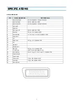
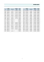
SPECIFICATIONS
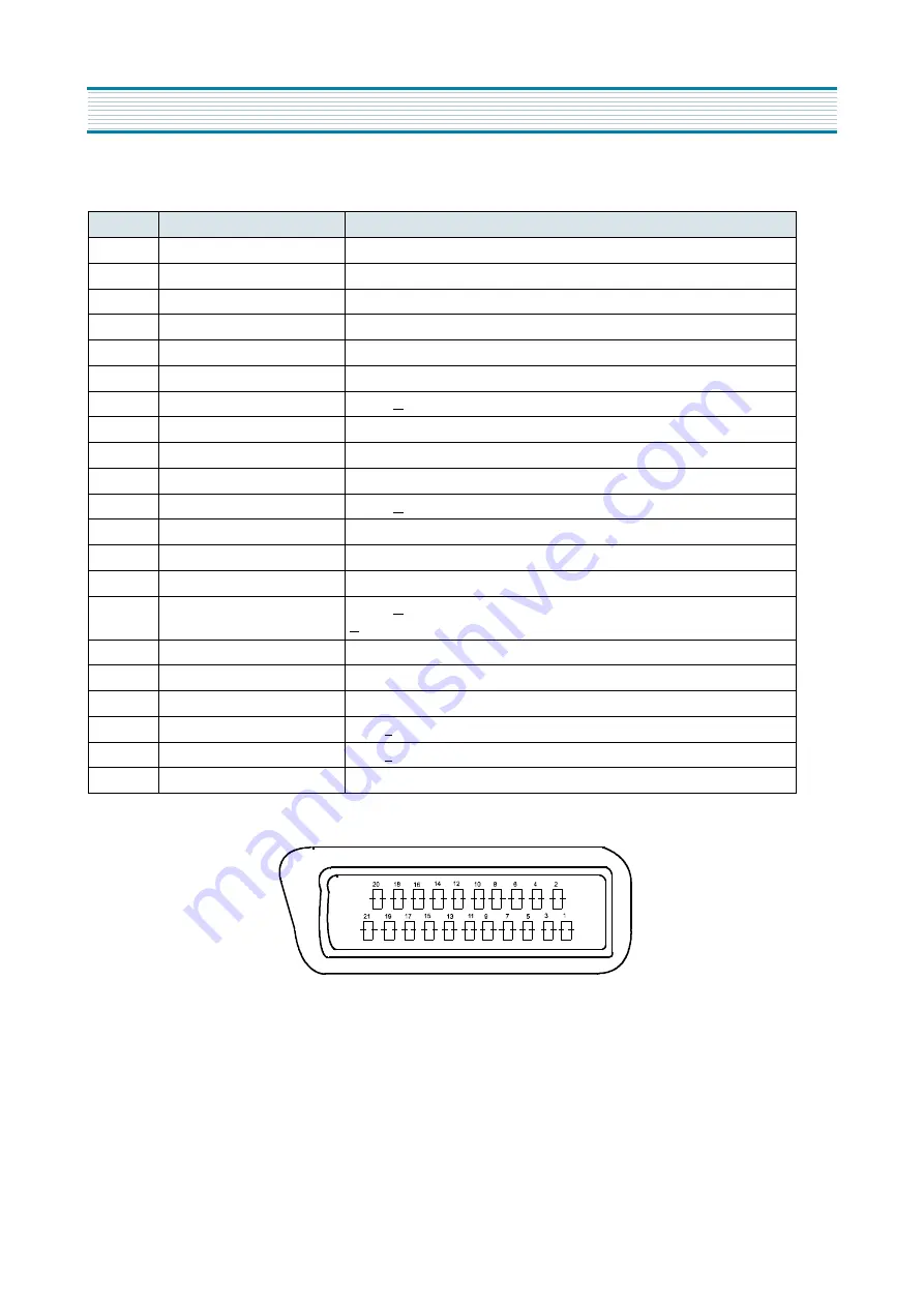
21Pin EURO-SCART
PIN
SIGNAL DESCRIPTION
MATCHING VALUE
1
Audio Output Right
0.5 Vrms, Impedance < 1k
Ω,
(RF 54% Mod)
2
Audio Input Right
0.5Vrms, Impedance > 10k
Ω
3
Audio Output Left
0.5 Vrms, Impedance < 1k
Ω,
(RF 54% Mod)
4
Audio Earth
5
Blue Earth
6
Audio Input Left
0.5Vrms, Impedance > 10k
Ω
7
Blue Input
0.7Vpp + 0.1V, Inpedance 75
Ω
8
Slow Switching
TV : 0 to 2V, AV : 4.5 to 12V, Impedance > 10k
Ω
9
Green Earth
10
N.C
11
Green Input
0.7Vpp + 0.1V, Impedance 75
Ω
12
N.C
13
Red Earth
14
Blanking Earth
15
Red Input
Chroma Input
0.7Vpp + 0.1V, Impedance 75
Ω
+ 3dB for a luminance signal of 1 Vpp
16
Fast Switching
0 to 0.4V : Logic “0”, 1 to 3V : Logic “1” , Impedance 75
Ω
17
Video Out Earth
18
Video In Earth
19
Video Output
1 Vpp + 3dB, Impedance 75
Ω
20
Video Input
1 Vpp + 3dB, Impedance 75
Ω
21
Common Earth
Summary of Contents for DTA-14V1
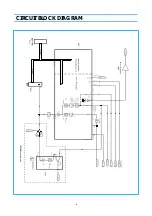
Page 26: ...6 CIRCUIT BLOCK DIAGRAM...
Page 29: ......
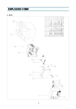
Page 30: ...10 EXPLODED VIEW 1 14V3...
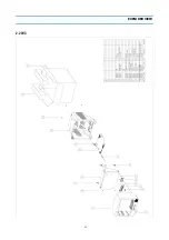
Page 31: ...11 EXPLODED VIEW 2 20V3...
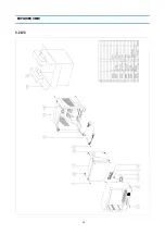
Page 32: ...12 EXPLODED VIEW 3 21V3...
Page 33: ...13 PRINTED CIRCUIT BOARD CIRCUIT DIAGRAM 6 SERVO SYSCON CEC CIRCUIT DIAGRAM T DECK...
Page 59: ...19 IC DESCRIPTION APPENDIX...
Page 62: ...22 APPENDIX IC DESCRIPTION...


