
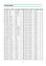

15
SCT1
4859303430
SOCKET CRT
PCS633A
SF1
5PK2960M--
FILTER SAW
K2960M
SW801
5S40101146
SW POWER PUSH
SS-160-7-B
I
T401
50D10A2---
TRANS DRIVE
TD-10A2
T402
50H0000211
FBT
1142.5109
T801
50M3535A1-
TRANS SMPS
2074.5046
I
U100
4859719930
TUNER VARACTOR
DT5-BF18D
X502
5XE12R000E
CRYSTAL QUARTZ
HC-49/U 12.00000MHZ 30PPM
Z501
5PYXT5R5MB
FILTER CERA
XT 5.5MB
Z502
5PYXT6R5MB
FILTER CERA
XT 6.5MB
ZZ200
PTMPJ0A670
PCB MAIN (RHU) AS
DTA-14V3VM
C315
CEXF2C470C
C ELECTRO
160V RUS 47MF (13X25) TP
C415
CEXF2E100V
C ELECTRO
250V RSS 10MF (10X20) TP
C603
CEXF1C471V
C ELECTRO
16V RSS 470MF (10X12.5)TP
C810
CCXB3D102K
C CERA
2KV B 1000PF K (TAPPING)
C813
CEXF2C101V
C ELECTRO
160V RSS 100MF (16X25) TP
C814
CEXF2C101V
C ELECTRO
160V RSS 100MF (16X25) TP
C823
CEXF1E102V
C ELECTRO
25V RSS 1000MF (13X20) TP
C832
CEXF1E102V
C ELECTRO
25V RSS 1000MF (13X20) TP
C840
CEXF1C222V
C ELECTRO
16V RSS 2200MF (13X25) TP
C841
CEXF1C222V
C ELECTRO
16V RSS 2200MF (13X25) TP
C861
CEXF1E102V
C ELECTRO
25V RSS 1000MF (13X20) TP
C965
CCXB3D102K
C CERA
2KV B 1000PF K (TAPPING)
ZZ200
PTMPJBA670
PCB MAIN M-10 AS
DTA-14V3VM
N001
4857417500
TERM PIN
DA-IB0214(D2.3/DY PIN)
N002
4857417500
TERM PIN
DA-IB0214(D2.3/DY PIN)
N003
4857417500
TERM PIN
DA-IB0214(D2.3/DY PIN)
N004
4857417500
TERM PIN
DA-IB0214(D2.3/DY PIN)
P601
485923162S
CONN WAFER
YW025-03 (STICK)
R305
RS02Z331JS
R M-OXIDE FILM
2W 330 OHM J SMALL
R402
RF01Z129J-
R FUSIBLE
1W 1.2 OHM J (TAPPING)
R415
RS02Z102JS
R M-OXIDE FILM
2W 1K OHM J SMALL
R450
RS02Z103JS
R M-OXIDE FILM
2W 10K OHM J SMALL
R802
RS02Z753JS
R M-OXIDE FILM
2W 75K OHM J SMALL
R803
RS02Z473JS
R M-OXIDE FILM
2W 47K OHM J SMALL
R804
RF02Z228K-
R FUSIBLE
2W 0.22 OHM K (TAPPING)
R808
RS02Z821JS
R M-OXIDE FILM
2W 820 OHM J SMALL
ZZ200
PTMPJRA670
PCB MAIN RADIAL AS
DTA-14V3VM
C101
CEXF1H100V
C ELECTRO
50V RSS 10MF (5X11) TP
C102
CEXF1H470V
C ELECTRO
50V RSS 47MF (6.3X11) TP
C106
CEXF1E221V
C ELECTRO
25V RSS 220MF (8X11.5) TP
C120
CCXB1H102K
C CERA
50V B 1000PF K (TAPPING)
C121
CEXF1H100V
C ELECTRO
50V RSS 10MF (5X11) TP
C305
CEXF1E221V
C ELECTRO
25V RSS 220MF (8X11.5) TP
C313
CMXM2A104J
C MYLAR
100V 0.1MF J (TP)
C320
CBXF1H104Z
C CERA SEMI
50V F 0.1MF Z (TAPPING)
C390
CMXM2A473J
C MYLAR
100V 0.047MF J (TP)
C401
CEXF1H470V
C ELECTRO
50V RSS 47MF (6.3X11) TP
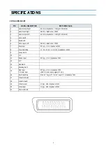
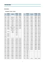
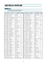
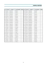
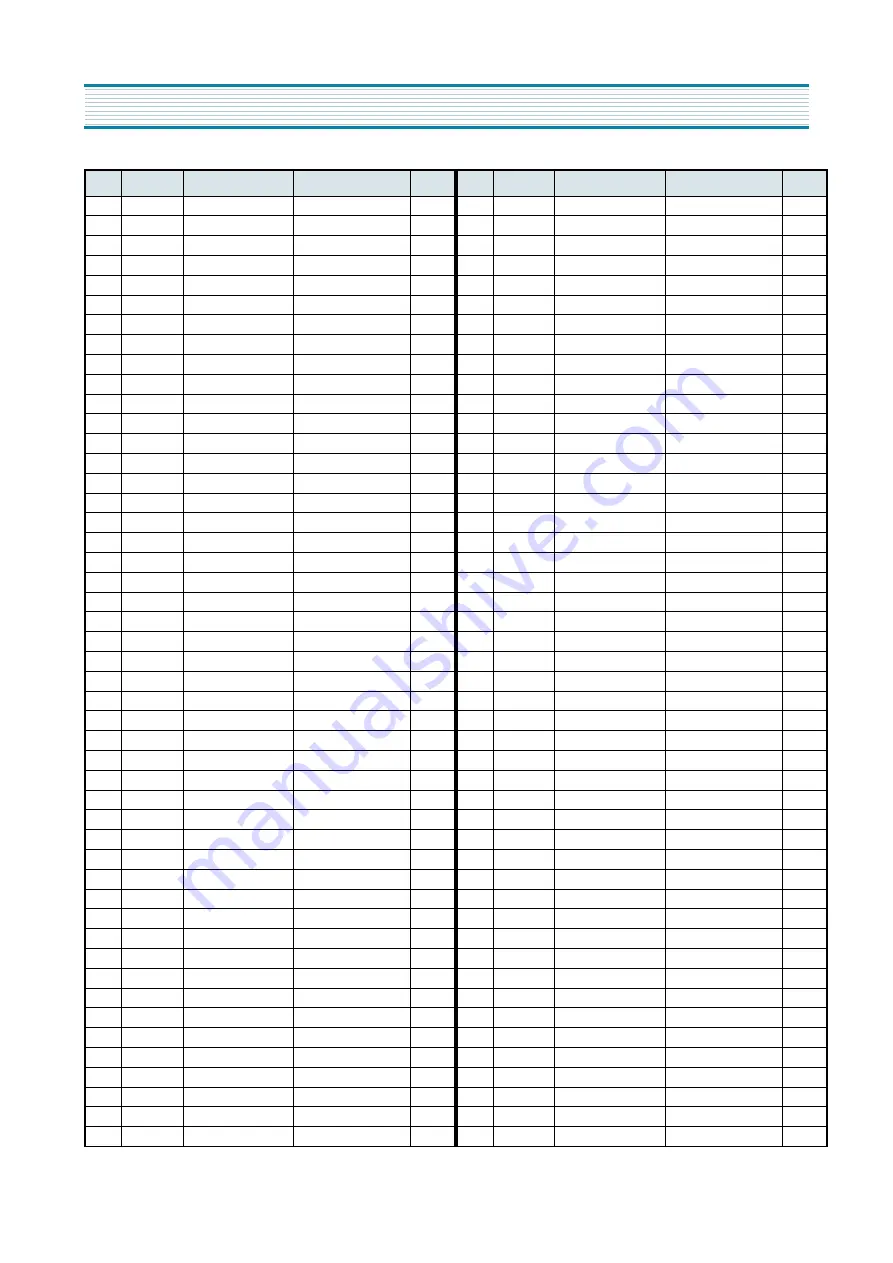
LOC.
PART CODE
PART NAME
PART DESCRIPTION
REMARK
C412
CEXF2C339V
C ELECTRO
160V RSS 3.3MF (8X16) TP
C414
CMXM2A104J
C MYLAR
100V 0.1MF J (TP)
C417
CMXL2E104K
C MYLAR
250V MEU 0.1MF K
C418
CCXB1H102K
C CERA
50V B 1000PF K (TAPPING)
C420
CCXB2H222K
C CERA
500V B 2200PF K (TAPPING)
C500
CEXF1H478V
C ELECTRO
50V RSS 0.47MF (5X11) TP
C501
CEXF1H100V
C ELECTRO
50V RSS 10MF (5X11) TP
C502
CEXF1H100V
C ELECTRO
50V RSS 10MF (5X11) TP
C504
CMXM2A332J
C MYLAR
100V 3300PF J (TP)
C509
CEXF1E470V
C ELECTRO
25V RSS 47MF (5X11) TP
C511
CMXM2A224J
C MYLAR
100V 0.22MF J
C512
CMXM2A224J
C MYLAR
100V 0.22MF J
C513
CBXF1H104Z
C CERA SEMI
50V F 0.1MF Z (TAPPING)
C514
CEXF1E101V
C ELECTRO
25V RSS 100MF (6.3X11) TP
C517
CEXF1H109V
C ELECTRO
50V RSS 1MF (5X11) TP
C519
CEXF1H229V
C ELECTRO
50V RSS 2.2MF (5X11) TP
C522
CEXF1H479V
C ELECTRO
50V RSS 4.7MF (5X11) TP
C524
CMXM2A104J
C MYLAR
100V 0.1MF J (TP)
C525
CCXB1H102K
C CERA
50V B 1000PF K (TAPPING)
C526
CMXM2A104J
C MYLAR
100V 0.1MF J (TP)
C527
CMXM2A473J
C MYLAR
100V 0.047MF J (TP)
C528
CEXF1E101V
C ELECTRO
25V RSS 100MF (6.3X11) TP
C530
CEXF1C101V
C ELECTRO
16V RSS 100MF (6.3X11) TP
C532
CEXF1H100V
C ELECTRO
50V RSS 10MF (5X11) TP
C533
CCXB1H102K
C CERA
50V B 1000PF K (TAPPING)
C537
CBXF1H104Z
C CERA SEMI
50V F 0.1MF Z (TAPPING)
C555
CEXF1C470V
C ELECTRO
16V RSS 47MF (5X11) TP
C560
CBXF1H104Z
C CERA SEMI
50V F 0.1MF Z (TAPPING)
C564
CEXF1E101V
C ELECTRO
25V RSS 100MF (6.3X11) TP
C565
CBXF1H104Z
C CERA SEMI
50V F 0.1MF Z (TAPPING)
C570
CCXB1H472K
C CERA
50V B 4700PF K (TAPPING)
C571
CCXB1H821K
C CERA
50V B 820PF K (TAPPING)
C580
CEXF1E221V
C ELECTRO
25V RSS 220MF (8X11.5) TP
C585
CCXB1H222K
C CERA
50V B 2200PF K (TAPPING)
C590
CXCH1H270J
C CERA
50V CH 27PF J (TAPPING)
C591
CXCH1H270J
C CERA
50V CH 27PF J (TAPPING)
C592
CBXF1H104Z
C CERA SEMI
50V F 0.1MF Z (TAPPING)
C593
CEXF1E101V
C ELECTRO
25V RSS 100MF (6.3X11) TP
C599
CEXF1H229V
C ELECTRO
50V RSS 2.2MF (5X11) TP
C600
CEXF1E101V
C ELECTRO
25V RSS 100MF (6.3X11) TP
C601
CEXF1H108V
C ELECTRO
50V RSS 0.1MF (5X11) TP
C602
CCXF1H103Z
C CERA
50V F 0.01MF Z (TAPPING)
C650
CEXF1E470V
C ELECTRO
25V RSS 47MF (5X11) TP
C770
CEXF1C101V
C ELECTRO
16V RSS 100MF (6.3X11) TP
C803
CCXF3A472Z
C CERA
1KV F 4700PF Z (T)
C804
CCXF3A472Z
C CERA
1KV F 4700PF Z (T)
C806
CEXF1H330V
C ELECTRO
50V RSS 33MF (6.3X11) TP
C807
CCXF1H473Z
C CERA
50V F 0.047MF Z (TAPPING)
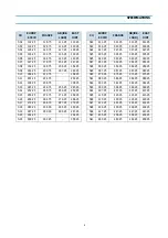
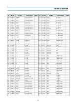
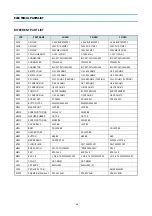
LOC.
PART CODE
PART NAME
PART DESCRIPTION
REMARK
ELECTRICAL PARTS LIST
Summary of Contents for DTA-14V1
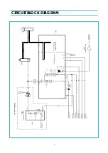
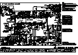
Page 26: ...6 CIRCUIT BLOCK DIAGRAM...
Page 29: ......
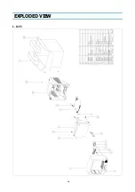
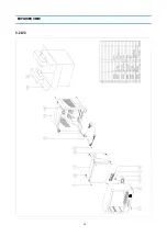
Page 30: ...10 EXPLODED VIEW 1 14V3...
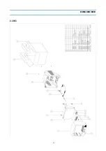
Page 31: ...11 EXPLODED VIEW 2 20V3...
Page 32: ...12 EXPLODED VIEW 3 21V3...
Page 33: ...13 PRINTED CIRCUIT BOARD CIRCUIT DIAGRAM 6 SERVO SYSCON CEC CIRCUIT DIAGRAM T DECK...
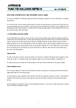
Page 59: ...19 IC DESCRIPTION APPENDIX...
Page 62: ...22 APPENDIX IC DESCRIPTION...