10
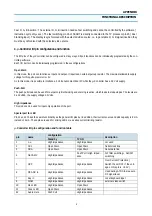
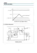
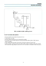
8-2-3. STR-F6653 protection circuits
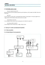
overcurrent protection function (OCP)
Overcurrent protection is performed pulse by pulse detecting at STR-F6653 pin 1 (OCP) the peak of the MOSFET drain current
in every pulse.
latch circuit
This circuit sustains an output low from the STR-F6653 internal oscillator and stops operation of the power supply when over-
voltage protection (OVP) and thermal shutdown (TSD) circuit are in operation
thermal shutdown circuit (TSD)
This circuit triggers the latch circuit when the frame temperature of STR-F6653 IC exceeds 140
°
C
overvoltage protection circuit (OVP)
This circuit triggers the latch circuit when the V
in
voltage exceeds 22V (typ.)
9. TV start-up, TV normal run and stand by mode operations
9-1. TV start-up operations
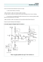
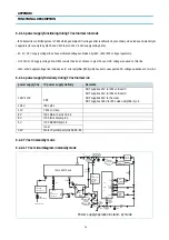
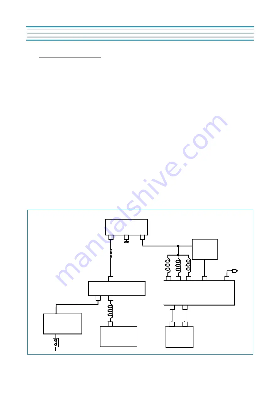
9-1-1. Schematic diagram for start-up operations
I823 REG 3.3V
IN GND OUT
1 2 3
RESET
PULSE
CIRCUIT
IN
OUT
63
60
54
56
61
L511
L510
L512
Vddc VddA Reset N Power
I501
MICROCONTROLLER PART
SCL SDA
3
2
5
6
3
4
2
D
I801 MOSFET AND
CONTROL IC
I702
EEPROM
SW801
POWER SWITCH
D801... D804
(GRAETZ BRIDGE)
L801
T801 SMPS TRANSFORMER
12
8V
Vddp
APPENDIX
FUNCTIONAL DESCRIPTION
Summary of Contents for DTA-14V1
Page 26: ...6 CIRCUIT BLOCK DIAGRAM...
Page 29: ......
Page 30: ...10 EXPLODED VIEW 1 14V3...
Page 31: ...11 EXPLODED VIEW 2 20V3...
Page 32: ...12 EXPLODED VIEW 3 21V3...
Page 33: ...13 PRINTED CIRCUIT BOARD CIRCUIT DIAGRAM 6 SERVO SYSCON CEC CIRCUIT DIAGRAM T DECK...
Page 59: ...19 IC DESCRIPTION APPENDIX...
Page 62: ...22 APPENDIX IC DESCRIPTION...

