background image

CP-093F Service Manual

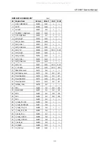
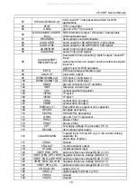
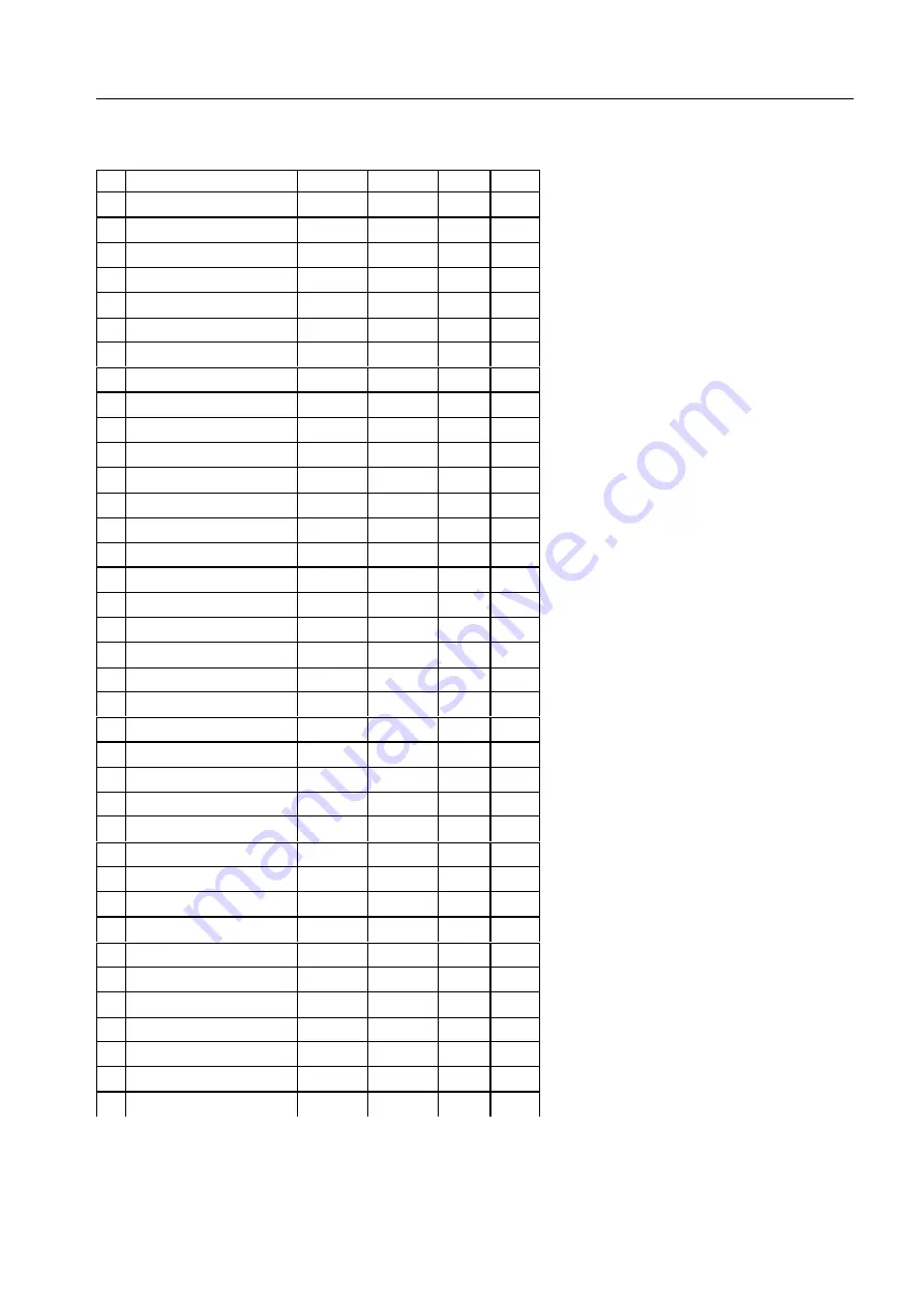
NVM DATA CHANGE LIST

(hex)

No Register Name

Address

Default

14H9

21H9

1

OCP_THRESHOLD

0x58F

0x91

<-

<-

2

DCXO

0x590

0x4E

<-

<-

3

AVLLEV

0x621

0x5

<-

<-

4

TELETEXT - Brightness

0x642

0x19

<-

<-

5

OSD - Brightness

0x644

0x7

<-

<-

6

Nor1_Bright

0x64A

0x23

<-

<-

7

Nor1_contrast

0x64B

0x2E

<-

<-

8

Nor1_Colour

0x64C

0x1C

<-

<-

9

Nor1_Sharpness

0x64D

0x23

<-

<-

10 Nor1_Tint

0x64E

0x20

0x1F

0x1F

11 Nor2_Bright

0x653

0x28

<-

<-

12 Nor2_Contrast

0x654

0x13

<-

<-

13 Nor2_Colour

0x655

0x19

<-

<-

14 Nor2_Sharpness

0x656

0x1B

<-

<-

15 Nor2_Tint

0x657

0x20

0x1F

0x1F

16 V - Linearity

0x667

0x2A

0x22

0x27

17 Peak White Level

0x671

0x1

<-

<-

18 Soft Clipping Level

0x672

0x5

0x7

0x7

19 PresetGainRGB

0x673

0x2A

0x1

0x7

20 PresetGainRGB

0x674

0x2A

0x1

0x7

21 PresetGainRGB

0x675

0x2A

0x1

0x7

22 Cathode_Drive

0x67B

0x1

<-

<-

23 RPA

0x680

0x1

0x2

0x2

24 Black Stretch

0x682

0x1

0x2

0x2

25 BSD

0x683

0x1

0x0

0x0

26 AAS

0x684

0x1

0x0

0x0

27 BCS

0x685

0x1

<-

<-

28 Y_delay_PAL_BG

0x686

0x5

<-

<-

29 Y_delay_SECAM_BG

0x687

0x8

<-

<-

30 Y_delay_PAL_DK

0x688

0x5

<-

<-

31 Y_delay_SCM_DK

0x689

0x5

<-

<-

32 Y_delay_PAL_I

0x68A

0x7

<-

<-

33 Y_delay_SECAM

0x68B

0x5

<-

<-

34 Y_delay_SECAM-L

0x68C

0x8

<-

<-

35 Y_delay_AV

0x68D

0xA

<-

<-

36 G2_Bright

0x68E

0x1A

<-

<-

37 G2_Contrast

0x68F

0x42

<-

<-

11

All manuals and user guides at all-guides.com

Summary of Contents for DTD-21H9

Page 1: ...parts list So if you need the latest parts information please refer to PPL Parts Price List in Service Information Center http svc dwe co kr DAEWOO ELECTRONICS Corp Service Manual Jan 2005 COLOR TELEVISION CHASSIS CP 093F MODEL DTD 21H9 SM No TCP093FEF0 All manuals and user guides at all guides com a l l g u i d e s c o m ...

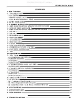
Page 2: ... 12 4 5 HORIZONTAL PICTURE CENTRING 12 4 6 EAST WEST CORRECTION 12 4 7 AGC 13 5 IC DESCRIPTION 14 5 1 UOC Series 14 5 1 1 IC MARKING AND VERSION 14 5 1 2 BLOCK DIAGRAM 15 5 1 3 PINNING 16 5 1 4 FEATURES 17 5 2 TDA8944J STEREO AUDIO AMPLIFIER 22 5 2 1 FEATURES 23 5 3 TDA8357J VERTICAL AMPLIFIER 25 5 3 1 TDA8357J 25 5 4 TDA6107AJE 28 5 4 1 Features 28 5 4 2 Pin description 28 5 5 24WC16 16KB EEPROM ...

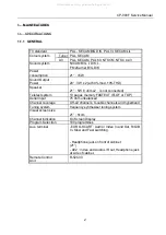
Page 3: ...Teletext system 10 pages memory FASTEXT FLOF or TOP Aerial input 75 ohm unbalanced Channel coverage Off air channels S cable channels and hyperband Tuning system frequency synthesiser tuning system Visual screen size 21 51cm Channel indication On Screen Display Program Selection 100 programmes Aux terminal EURO SCART Audio Video In and Out R G B In Slow and Fast switching Headphone jack on front o...

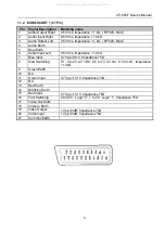
Page 4: ... kΩ 7 Blue Input 0 7 Vpp 0 1V Impedance 75Ω 8 Slow Switching TV 0 to 2V AV 16 9 4 5 to 7V AV 4 3 9 5 to 12V Impedance 10 kΩ 9 Green Earth 10 N C 11 Green Input 0 7 Vpp 0 1V Impedance 75Ω 12 N C 13 Red Earth 14 Blanking Earth 15 Red Input 0 7 Vpp 0 1V Impedance 75Ω 16 Fast Switching 0 to 0 4V Logic 0 1 to 3V Logic 1 Impedance 75Ω 17 Video Out Earth 18 Video In Earth 19 Video Output 1 Vpp 3dB Impeda...

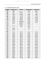
Page 5: ...25 471 25 C22 479 25 479 25 479 25 479 25 C23 487 25 487 25 487 25 487 25 C24 495 25 495 25 495 25 495 25 C25 503 25 503 25 503 25 503 25 C26 511 25 511 25 511 25 511 25 C27 519 25 519 25 519 25 519 25 C28 527 25 527 25 527 25 527 25 C29 535 25 535 25 535 25 535 25 C30 543 25 543 25 543 25 543 25 C31 551 25 551 25 551 25 551 25 C32 559 25 559 25 559 25 559 25 C33 567 25 567 25 567 25 567 25 C34 57...

Page 6: ...823 25 823 25 823 25 C66 831 25 831 25 831 25 831 25 C67 839 25 839 25 839 25 839 25 C68 847 25 847 25 847 25 847 25 C69 855 25 855 25 855 25 855 25 C70 863 25 863 25 863 25 863 25 C71 69 25 C72 76 25 C73 83 25 C74 90 25 C75 97 25 C76 59 25 C77 93 25 S01 105 25 104 75 103 25 105 25 S02 112 25 116 75 111 25 112 25 S03 119 25 128 75 119 25 119 25 S04 126 25 140 75 127 25 126 25 S05 133 25 152 75 135...

Page 7: ...351 25 351 25 S28 359 25 359 25 359 25 359 25 S29 367 25 367 25 367 25 367 25 S30 375 25 375 25 375 25 375 25 S31 383 25 383 25 383 25 383 25 S32 391 25 391 25 391 25 391 25 S33 399 25 399 25 399 25 399 25 S34 407 25 407 25 407 25 407 25 S35 415 25 415 25 415 25 415 25 S36 423 25 423 25 423 25 423 25 S37 431 25 431 25 431 25 431 25 S38 439 25 439 25 439 25 439 25 S39 447 25 447 25 447 25 447 25 S4...

Page 8: ...pment Discharge the high potential of the picture tube before handling the tube The picture tube is highly evacuated and if broken glass fragments will be violently expelled If any Fuse in this TV receiver is blown replace it with the FUSE specified in the Replacement Parts List When replacing a high wattage resistor metal oxide film resistor in the circuit board keep the resistor 10 mm away from ...

Page 9: ...thin range Cycle trough option bits OK key Toggle bits in option byte Order Item Default setting 1 HOR CEN 2 RED GAIN 3 GRN GAIN 4 BLUE GAIN 5 RED BIAS 6 GRN BIAS 7 AGC LEVEL 8 G2 SCREEN 9 OPTION1 10 OPTION2 11 AVL 12 PARABOLA 13 HOR WIDTH 14 CORNER T 15 CORNER B 16 HOR PARAL 17 V LINEAR 18 V SLOPE 19 EW TRAPEZ 20 S CORRECT 21 VERT CENT 22 VERT SIZE 3 3 MICROCONTROLLER CONFIGURATION OPTION BITS Th...

Page 10: ...AM L Dolby Virtual ON SVHS3 enable TUNER OPTIONS 00 Philips 01 Not used 10 Alps 11 Parstnic DW 3 5 OPTION 2 B7 B6 B5 B4 B3 B2 B1 B0 1 JVC remote control AVL control OFF PICTURE TILT ON 14 AV2 OFF Full ATSS Double Window Enabled 0 Fixed to 0 Daewoo Remote control AVL control ON PICTURE TILT OFF 21 AV2 ON Basic ATSS Double Window Disabled n u Must be set to 1 for future compa tibility 9 All manuals ...

Page 11: ...de To switch the TV set into NVM EDITOR mode use the user remote control and press on ON ENTER key The NVM EDITOR window will appear on the screen This mode allow you to access all data stored in NVM The current NVM address is given in column ADDR in both DECimal and HEXadecimal format The column DATA gives the value contained at selected address in both DECimal and HEXadecimal format 4 Navigation...

Page 12: ...0x1F 16 V Linearity 0x667 0x2A 0x22 0x27 17 Peak White Level 0x671 0x1 18 Soft Clipping Level 0x672 0x5 0x7 0x7 19 PresetGainRGB 0x673 0x2A 0x1 0x7 20 PresetGainRGB 0x674 0x2A 0x1 0x7 21 PresetGainRGB 0x675 0x2A 0x1 0x7 22 Cathode_Drive 0x67B 0x1 23 RPA 0x680 0x1 0x2 0x2 24 Black Stretch 0x682 0x1 0x2 0x2 25 BSD 0x683 0x1 0x0 0x0 26 AAS 0x684 0x1 0x0 0x0 27 BCS 0x685 0x1 28 Y_delay_PAL_BG 0x686 0x...

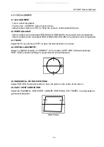
Page 13: ...he desired colour temperature 4 3 FOCUS Adjust the Focus volume on FBT to have the best resolution on screen 4 4 VERTICAL GEOMETRY Adjust V LINEAR linearity S CORRECT S Correction VERT SIZE Vertical amplitude VERT CENT vertical centring to compensate for vertical distortion 4 5 HORIZONTAL PICTURE CENTRING Adjust HOR CEN Horizontal centre to have the picture in the centre of the screen 4 6 EAST WES...

Page 14: ...e correct for the tuner fitted on the chassis See above how to change option bits Adjust the antenna signal level at 62 dBµV Tune a colour bar pattern Find the AGC item in service mode Press the key OK on the remote keypad and wait until AGC level stabilise to the optimum value 13 All manuals and user guides at all guides com ...

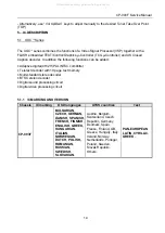
Page 15: ...decoder with 10 page text memory Multi standard stereo decoder BTSC stereo decoder Digital sound processing circuit Digital video processing circuit 5 1 1 IC MARKING AND VERSION Chassis IC marking OSD languages ATSS countries Text CP 093F BULGARIAN CZECH GERMAN DANISH SPANISH FRENCH FINNISH ENGLISH GREEK HUNGARIAN ITALIAN NORWEGIAN DUTCH POLISH ROMANIAN RUSSIAN SWEDISH SLOVAKIAN Austria Belgium Sw...

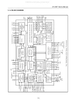
Page 16: ...CP 093F Service Manual 5 1 2 BLOCK DIAGRAM 15 All manuals and user guides at all guides com a l l g u i d e s c o m ...

Page 17: ... or I2C bus clock line 22 P1 3 T1 port 1 3 or Counter Timer 1 input 23 P0 0 I2SDI1 O port 0 0 or I2S digital input 1 or I2S digital output 24 P0 1 I2SDO1 port 0 1 or I2S digital output 1 25 P0 2 I2SDO2 port 0 2 or I2S digital output 2 26 P0 3 I2SCLK port 0 3 or I2S clock 27 P0 4 I2SWS port 0 4 or I2S word select 28 VSSC2 Ground 29 VDDC2 digital supply to core 1 8 V 30 P1 1 T0 port 1 1 or Counter T...

Page 18: ...put or composite H V timing output 64 SVM scan velocity modulation output 65 CVBSO PIP CVBS PIP output 66 AUDOUTHPR audio output for headphone channel right signal 67 AUDOUTHPL audio output for headphone channel left signal 68 AUDOUTLSR audio output for audio power amplifier right signal 69 AUDOUTLSL audio output for audio power amplifier left signal 70 C2 C3 chroma 2 3 input 71 CVBS3 Y3 CVBS3 Y3 ...

Page 19: ...rence current input 103 VSC vertical sawtooth capacitor 104 VIFIN2 IF input 2 105 VIFIN1 IF input 1 106 VDRA vertical drive A output 107 VDRB vertical drive B output 108 EWD AVL 1 East West drive output or AVL capacitor 109 DECBG bandgap decoupling 110 SECPLL SECAM PLL decoupling 111 GND1 ground 1 for TV processor 112 PH1LF phase 1 filter 113 PH2LF phase 2 filter 114 VP1 1st supply voltage TV proc...

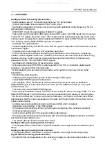
Page 20: ...es Internal base band delay line Indication of the Signal to Noise ratio of the incoming CVBS signal Linear RGB YPBPR input with fast insertion YUV interface When this feature is not required some pins can be used as additional RGB YPBPR input It is also possible to use these pins for additional CVBS or Y C input CVBS YX and CX Tint control for external RGB YPBPR signals Scan Velocity Modulation o...

Page 21: ...ls AVL Automatic Volume Levelling circuit for the headphone channel Digital input crossbar switch for all digital signal sources and destinations Digital output crossbar for exchange of channel processing functionality Digital audio input interface stereo I2S input interface Digital audio output interface stereo I2S output interface Audio interfaces and switching AV stereo versions without Audio D...

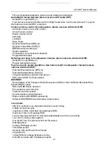
Page 22: ... with Audio DSP Extended Pseudo Stereo EPS 5 Extended Spatial Stereo ESS 6 Virtual Dolby Surround VDS 422 423 1 SRS 3D and SRS TruSurround 4 RDS RBDS Demodulation of the European Radio Data system RDS or the USA Radio Broadcast Data System RBDS signal RDS and RBDS block detection Error detection and correction Fast block synchronisation Synchronisation control flywheel Mode control for RDS RBDS pr...

Page 23: ...tion for 16 9 screens Serial and Parallel Display Attributes Single Double Quadruple Width and Height for characters Smoothing capability of both Double Size Double Width Double Height characters Scrolling of display region Variable flash rate controlled by software Soft colours using CLUT with 4096 colour palette Globally selectable scan lines per row 9 10 13 16 and character matrix 12x9 12x10 12...

Page 24: ...hermally protected Pin description Pin Symbol Description 1 OUT1 negative loudspeaker terminal 1 2 GND1 ground channel 1 3 Vcc1 supply voltage channel 1 4 OUT1 positive loudspeaker terminal 1 5 n c not connected 6 IN1 positive input1 7 n c not connected 8 IN1 negative input1 9 IN2 negative input2 10 MODE mode selection input 11 SVR half supply voltage decoupling ripple rejection 12 IN2 positive in...

Page 25: ...CP 093F Service Manual Block diagram TDA8946J 24 All manuals and user guides at all guides com ...

Page 26: ... coil in combination with single positive supply voltages The IC is constructed in a Low Voltage DMOS LVDMOS process that combines bipolar CMOS and DMOS devices DMOS transistors are used in the output stage because of the absence of second breakdown 5 3 1 TDA8357J Features Few external components Highly efficient fully DC coupled vertical bridge output circuit Vertical flyback switch with short ri...

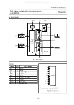
Page 27: ... p VI bias 0 Vi p p 0 OUTB OUTA FEEDB Fig 1 Block diagram PINNING SYMBOL PIN DESCRIPTION INA 1 input A INB 2 input B VP 3 supply voltage OUTB 4 output B GND 5 ground VFB 6 flyback supply voltage OUTA 7 output A GUARD 8 guard output FEEDB 9 feedback input handbook halfpage INA INB VP OUTB GND VFB OUTA GUARD FEEDB 1 2 3 4 5 6 7 8 9 TDA8357J MGS804 Fig 2 Pin configuration The exposed die pad is conne...

Page 28: ...F C3 100 nF D5 12 V C1 47 µF 100 V C4 100 nF C2 220 µF 25 V R D2 1 5 Ω 2 1 INA INB FEEDB GUARD R GRD 12 kΩ R CV1 2 2 kΩ 1 R CV2 2 2 kΩ 1 R S 2 7 kΩ MGS807 INPUT AND FEEDBACK CIRCUIT GUARD CIRCUIT TDA8357J 9 7 4 5 8 6 3 GND V P V FB OUTB OUTA V i p p V I bias 0 V I bias V i p p 0 M2 M5 M4 M1 M3 D1 D3 D2 Fig 4 Application diagram f vert 50 Hz t FB 640 µs I I bias 400 µA I i p p 475 µA I o p p 1 4 A ...

Page 29: ... No external components required Very simple application Single supply voltage of 200V Internal reference voltage of 2 5 V Fixed gain of 81 Black current stabilisation BCS circuit with voltage window from 1 8 to 6 V and current window form 100uA to 10mA Thermal protection Internal protection against positive flashover discharges appearing on the CRT 5 4 2 Pin description Pin Symbol Description 1 V...

Page 30: ...utput 6 SCL Serial clock 7 WP Write control 8 Vcc Supply voltage 4 Vss Ground The memory device is compatible with the I2C memory standard This is a two wire serial interface that uses a bi directional data bus and serial clock The memory carries a built in 4 bit unique device type identifier code 1010 in accordance with the I2C bus definition Serial Clock SCL The SCL input is used to strobe all d...

Page 31: ...5 6 1 Functions of Each Terminal 5 6 2 Block Diagram Connection diagram CP 093F Service Manual 5 6 STR W6753 4 30 All manuals and user guides at all guides com a l l g u i d e s c o m ...

Page 32: ...CP 093F Service Manual 31 All manuals and user guides at all guides com ...

Page 33: ...CP 093F Service Manual 32 All manuals and user guides at all guides com ...

Page 34: ...ion stop voltage 4 3 VIN off 8 8 9 7 10 6 V Circuit current in operation 4 3 IIN on 6 mA Circ current in non operation 4 3 IIN off 100 µA Maximum ON time 1 3 TON max 27 5 32 5 39 0 µSEC Minimum ON time 1 3 TON min 0 4 0 8 1 2 µSEC OVP operation voltage 4 3 VIN OVP 25 5 27 5 29 9 V Latch circuit release voltage 4 3 VIN Loff 6 0 7 2 8 5 V 33 All manuals and user guides at all guides com ...

Page 35: ...x1 4 x1 8 Search Title A11 Track CD Chapter Time search Repeat Disc Title Chapter A B DVD X 0 0 0 Disc Track A B CD VCD 0 0 0 Disc Track Dir MP3 X 0 0 Resume Stop Function ZOOM x2 x4 Screen Saver On Off MP3 CDDA Stop Still Disc Open Parental Lock Control jpg files playback Rotation Slide show Audio Switchable Output Digital Coaxial LPCM BITSTREAM SELECTION Program Play CDDA MP3 only 4 3 P S 4 3LB ...

Page 36: ...t Data In 10 GND 11 DVD 3 3VZ 12 DVD 3 3V 13 GND 14 DVD 1 8V 15 GND 16 DVD 5V 17 DVD 5V 18 GND 19 DVD 12V No of PIN DISCRIPTION 1 Not Connected 2 Not Connected 3 Host Data Out 4 Request 5 Mute 6 SPDIF 7 GND 8 Digital Data 9 Digital Data 10 Digital Data 11 SCK 12 GND 13 GND 14 GND 15 Host Strobe 35 All manuals and user guides at all guides com a l l g u i d e s c o m ...

Page 37: ...bserve defected connector lines c Check communication lines Host Data In Out Acknowledge Host strobe Request B DVD Firmware Version check OPEN DISPLAY UP DOWN LEFT RIGHT C Region Code check OPEN 0 5 2 0 UP DOWN LEFT RIGHT Check Region with Title Default Europe is Region 2 Exception above you must substitute DVD module by module CP 093F 21 INCH is NO SOUND when AV2 PCB is not connected 36 All manua...

Page 38: ...01 1STRW6754 ICPOWER STR W6754 0000A 4857024600 HEATSINK ALEXB K 0000B 7174300811 SCREWTAPPTITE TT2RND3X8MFZN I802 1LTV817C ICPHOTOCOUPLER LTV 817C I803 1K1A78R05A ICREGULATOR K1A78R05AP15 0V1 0ATO 220 I804 PT22SW7800 HEATSINKASS Y 1K1A78R05A 7174300811 00001 1K1A78R05A ICREGULATOR K1A78R05AP15 0V1 0ATO 220 0000A 4857027800 HEATSINK ALEX 0000B 7174300811 SCREWTAPPTITE TT2RND3X8MFZN I805 PT32SW7800...

Page 39: ...K T146 BR QC802 T2SC2412KB TRCHIP 2SC2412K T146 BR QC805 T2SC2412KB TRCHIP 2SC2412K T146 BR QCD40 T2SC2412KB TRCHIP 2SC2412K T146 BR QCD41 T2SC2412KB TRCHIP 2SC2412K T146 BR LOC PARTCODE PARTNAME DESCRIPTION REMARK QCD42 T2SC2412KB TRCHIP 2SC2412K T146 BR RC103 HRFT123JBA RCHIP 1 1012KOHMJ1608 RC104 HRFT683JBA RCHIP 1 1068KOHMJ1608 RC114 HRFT473JBA RCHIP 1 1047KOHMJ1608 RC115 HRFT101JBA RCHIP 1 10...

Page 40: ... 6 E40 4856310300 EYELET BSRT0 2 R1 6 E41 4856310600 EYELET BSRT0 2 R2 3 E42 4856310600 EYELET BSRT0 2 R2 3 E43 4856310600 EYELET BSRT0 2 R2 3 E44 4856310600 EYELET BSRT0 2 R2 3 E5 4856310600 EYELET BSRT0 2 R2 3 E6 4856310600 EYELET BSRT0 2 R2 3 E8 4856310600 EYELET BSRT0 2 R2 3 P601 485923172S CONNWAFER YW025 04 STICK P701 485923172S CONNWAFER YW025 04 STICK P801A 4857417500 TERMPIN DA IB0214 D2 ...

Page 41: ...0KV TAP SG02 4SG0DX0001 SPARKGAP SSG 102 A1 1 0KV TAP SG03 4SG0DX0001 SPARKGAP SSG 102 A1 1 0KV TAP SW01 5S50101Z90 SWTACT THVV502GDA LOC PARTCODE PARTNAME DESCRIPTION REMARK SW02 5S50101Z90 SWTACT THVV502GDA SW03 5S50101Z90 SWTACT THVV502GDA SW04 5S50101Z90 SWTACT THVV502GDA SW05 5S50101Z90 SWTACT THVV502GDA SW11 5S50101Z90 SWTACT THVV502GDA SW12 5S50101Z90 SWTACT THVV502GDA SW13 5S50101Z90 SWTAC...

Page 42: ...45 85801065GY WIRECOPPER AWG221 0 65TINCOATING J046 85801065GY WIRECOPPER AWG221 0 65TINCOATING J047 85801065GY WIRECOPPER AWG221 0 65TINCOATING J048 85801065GY WIRECOPPER AWG221 0 65TINCOATING J049 85801065GY WIRECOPPER AWG221 0 65TINCOATING J050 85801065GY WIRECOPPER AWG221 0 65TINCOATING J051 85801065GY WIRECOPPER AWG221 0 65TINCOATING J052 85801065GY WIRECOPPER AWG221 0 65TINCOATING J053 85801...

Page 43: ...G 4 7UHK AXIAL3 5MM L510 5CPZ479K02 COILPEAKING 4 7UHK AXIAL3 5MM L512 5CPZ479K02 COILPEAKING 4 7UHK AXIAL3 5MM L513 5CPZ479K02 COILPEAKING 4 7UHK AXIAL3 5MM L514 5CPZ479K02 COILPEAKING 4 7UHK AXIAL3 5MM L515 5CPZ479K02 COILPEAKING 4 7UHK AXIAL3 5MM L516 5CPZ479K02 COILPEAKING 4 7UHK AXIAL3 5MM L517 5CPZ479K02 COILPEAKING 4 7UHK AXIAL3 5MM LOC PARTCODE PARTNAME DESCRIPTION REMARK L518 5CPZ479K02 C...

Page 44: ...HMJ R844 RD AZ472J RCARBONFILM 1 64 7KOHMJ R845 85801065GY WIRECOPPER AWG221 0 65TINCOATING R910 RD 2Z102J RCARBONFILM 1 21KOHMJ R911 RD 2Z102J RCARBONFILM 1 21KOHMJ R912 RD 2Z102J RCARBONFILM 1 21KOHMJ R913 RD AZ101J RCARBONFILM 1 6100OHMJ R914 RD AZ101J RCARBONFILM 1 6100OHMJ R915 RD AZ101J RCARBONFILM 1 6100OHMJ R921 RD AZ221J RCARBONFILM 1 6220OHMJ R922 RD AZ221J RCARBONFILM 1 6220OHMJ R923 RD...

Page 45: ...44 CP 093 F Service Manual 8 EXPLODED VIEW 8 2 DTD 21H9 All manuals and user guides at all guides com ...

Page 46: ...45 CP 093 F Service Manual 9 Schematic Diagram All manuals and user guides at all guides com a l l g u i d e s c o m ...

Reviews: