Service manual CP-785AF
- 35 -
High impedance
This mode can be used for input only operation of the port.
Special port for LED
Pin 10 and 11 have the same functionality as the general I/O pins but in addition, their current source
and sink capacity is 8 mA instead of 4 mA. These pins are used for driving LED’s via a series current
limiting resistor.
µ
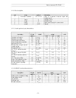
-Controller I/O pin configuration and function table
pin
name
configuration
description
Stand by
TV ON
1
n.u.
High impedance
High impedance
not used
2
SCL
Open Drain
Open Drain
Serial clock line
3
SDA
Open Drain
Open Drain
Serial data line
4
5
OCP
High impedance
High impedance
Over Current Protection
( Switch the set OFF if
the voltage on this pin is
<2.33V )
6
-
High impedance
High impedance
For factory use only
7
Key in
High impedance
High impedance
Local keyboard input
8
S/SW
High impedance
See table above
external video switch
10
Red LED
High impedance
Open Drain
11
Green LED
Open Drain
High impedance
62
Audio mute
Push Pull
Push Pull
High in stand by mode
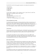
5-5 Sound processing
Analogue sound IF - input section
The input pins and ANA_IN- offer the possibility to connect sound IF sources to the MSP
3415D. The analogue-to-digital conversion of the preselected sound IF signal is done by an A/D
converter, whose output is used to control an analogue automatic gain circuit (AGC), providing an
optimal level for a wide range of input levels.
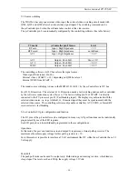
Quadrature Mixers
The digital input coming from the integrated A/D converter may contain audio information at a
frequency range of theoretically 0 to 9 MHz corresponding to the selected standards. By means of two
programmable quadrature mixers, two different audio sources ; for example, NICAM and FM-mono,
may be shifted into baseband position.
Phase and AM discrimination
The filtered sound IF signals are demodulated by means of the phase and amplitude discriminator block.
On the output, the phase and amplitude is available for further processing. AM signals are derived from
the amplitude information, whereas the phase information serves for FM and NICAM demodulation.
Summary of Contents for DTE-21U6TH
Page 15: ...Service manual CP 785AF A 14...
Page 18: ...Service manual CP 785AF 17...
Page 30: ...Service manual CP 785AF 29 5 Circuit description 5 1 Block diagram...
Page 60: ...Service manual CP 785AF 59 7 Exploded view...
Page 61: ...Service manual CP 785AF 60 8 PCB Layout...
Page 62: ...S ervice manual CP 785AF 61 9 Circuit Diagram...


