Service manual CP-785AF
- 44 -
.
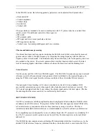
If the TV set was on normal run mode before switching off, the microcontroller delivers
horizontal drive voltage at pin 33 and picture appears on screen.
.
If the TV set was on stand-by mode before switching off, the microcontroller switches TV
set to stand-by mode, decreasing power pin voltage (pin 63). This matter will be explained
on paragraph 5-9-2-b.
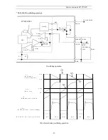
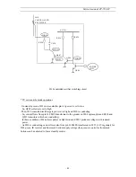
* Reset pulse circuit
3.3V
3.0V
3.0V
1.2V
1.2V
0V
DC supply voltage
I823
pin 3
reset pulse
I501
pin 60
from I823
pin 3
R591
220
Ω
D591
DZ2.4
R593
10K
Ω
R592
10k
Ω
Q510
R594
10K
Ω
Q511
C501
50V
10
µ
F
to I501
pin 60
+
0
V
Reset pulse circuit and corresponding waveforms
Summary of Contents for DTE-21U6TH
Page 15: ...Service manual CP 785AF A 14...
Page 18: ...Service manual CP 785AF 17...
Page 30: ...Service manual CP 785AF 29 5 Circuit description 5 1 Block diagram...
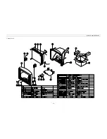
Page 60: ...Service manual CP 785AF 59 7 Exploded view...
Page 61: ...Service manual CP 785AF 60 8 PCB Layout...
Page 62: ...S ervice manual CP 785AF 61 9 Circuit Diagram...


