Service manual CP-785AF
- 45 -
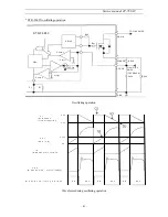
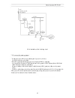
* Reset pulse circuit operations description
- When DC supply voltage from I823 regulator starts rising (from 0V to 1.2V), no current flows
through D591 zener diode. So, Q510 is in off mode.
Also V
be Q511
=Vcc/2 -Vcc = -Vcc/2 > -0.6V. So, Q511 is in off mode.
Then, no voltage reaches I501 pin 60.
- When this voltage reaches 1.2 V, Q510 stays in off mode
but V
be Q511
= -0.6V. So, Q511 is switched on and starts driving DC supply voltage to I501 pin 60.
- When the DC supply voltage reaches (2.4V +0.6V ) =3.0V, Q510 starts conducting but as the Q511
base-emitter voltage is the same as the collector-emitter voltage of the saturated Q510, Q511 switches
off and no voltage reaches I501 pin 60.
- If the DC supply voltage decreases below 3 V, Q510 switches off immediately. Q511 starts
conducting, pulling I501 pin 60 high.
At the same time, it discharges the reset capacitor C501. Discharging this capacitor is necessary to
garantee a defined reset pulse duration.
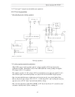
5-9-2 TV normal run and stand-by mode operations
Depending on remote control commands, I501 microcontroller part pin 63 (power) is set to:
- high for normal run mode
- low for stand-by mode
a) TV on normal run mode
* I501 microcontroller part pin 63 (power) effect
I501 microcontroller part pin 63 (power) is connected to the following circuit:
I 8 1 0
C O N T R O L L E D
R E C T I F I E R
R 8 2 0
R 8 3 0
C 8 3 0
R 8 2 9
Q 8 0 8
6 V D C
1 1 V D C
R 8 7 0
D 8 1 1
Q 8 1 1
Q 8 0 9
Q 8 0 7
Q 8 1 0
L O W
L O W
L O W
L O W
H I G H
H I G H
C O N D U C T I N G
P O W E R
H I G H
N O T
C O N D U C T I N G
I501 microcontroller part pin 63 (POWER) effect
Summary of Contents for DTE-21U6TH
Page 15: ...Service manual CP 785AF A 14...
Page 18: ...Service manual CP 785AF 17...
Page 30: ...Service manual CP 785AF 29 5 Circuit description 5 1 Block diagram...
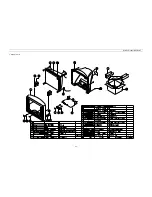
Page 60: ...Service manual CP 785AF 59 7 Exploded view...
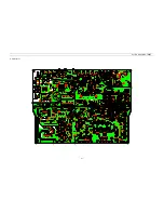
Page 61: ...Service manual CP 785AF 60 8 PCB Layout...
Page 62: ...S ervice manual CP 785AF 61 9 Circuit Diagram...

