background image

15

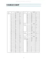
VOLTAGE CHART

MODE

LOC

PIN

ON

OFF

C

5.02

0

Q201

E

3.32

3.28

B

2.49

2.48

C

38.6

42.28

Q401

E

0

0

B0

0

C

132

0

Q402

E

0

0

B0

0

C

0.59

0

Q403

E

0

0

B

0

0.66

C

10.1

0

Q404

E

0

0

B0

0

C

9.71

0

Q602

E

1.69

0

B

2.31

0

C

5.02

4.99

Q701

E

0

0

B0

0

C

5.02

5

Q702

E

0

0

B0

0

MODE

LOC

PIN

ON

OFF

C

5.02

5

Q703

E

0

0

B0

0

C

4.93

4.9

Q704

E

4.95

4.92

B

4.32

4.29

C

5.02

4.2

Q707

E

0.21

5

B

0.07

4.9

C

2.89

0

Q760

E

0

0

B

0

0.68

C

0.4

0

Q804

E

133.1

119.38

B

132.6

118.96

C

12.31

5

Q805

E

5.02

10.88

B

5.6

5.59

C

4.01

0

Q851

E

0

0

B

0

0.68

All manuals and user guides at all-guides.com

all-guides.com

Summary of Contents for DTQ-14J4FCCN

Page 1: ...5FSPN 20V4FSPN DTQ 14U1FSPN 20U1FSPN S M No CN001N 010R1 Jun 2002 U S A Canada Middle America AC 110V Mexico Chile Peru AC 220V DAEWOO ELECTRONICS CO LTD http svc dwe co kr DTQ 14U1FS N DTQ 14V5FCN DT...

Page 2: ...12 VOLTAGE CHART 13 WAVEFORMS 16 SCHEMATIC DIAGRAM 20 EXPLODED VIEW 21 ELECTRICAL PARTS LIST 29 IC DESCRIPTION 1 TROUBLE SHOOTING CHARTS 8 NO POWER 8 NO PICTURE 9 NO SOUND 10 CH DON T STOP 11 NO COLOR...

Page 3: ...HIS TUBE DOES NOT EMIT X RAYS WHEN THE HIGH VOLT AGE IS AT THE FACTORY SPECIFIED LEVEL THE PROPER VALUE IS GIVEN IN THE APPLICABLE SCHEMATIC OPERATION AT HIGHER VOLT AGES MAY CAUSE A FAILURE OF THE PI...

Page 4: ...orrected imme diately GRAPHIC SYMBOLS The lightning flash with arrowhead symbol within an equilateral triangle is intended to alert the service personnel to the presence of uninsu lated dangerous volt...

Page 5: ...ed installations using a commercial mounting kit must follow the factory approved mounting instructions A receiver mounted to a shelf or platform must retain its original feet or the equivalent thickn...

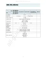
Page 6: ...ING RANGES VHF 2 13 12 UHF 14 69 56 CATV 1 125 125 SOUND OUTPUT 1 3 W 1 3 W 1 3 W 1 3 W SPEAKER 3 W 8 ohm ANTENNA INPUT IMPEDANCE 75 ohm Unbalanced AUXILIARY INPUT TERMINAL Front Video Audio Rear Vide...

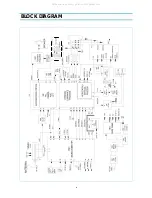
Page 7: ...6 BLOCK DIAGRAM A MUTE H 5 All manuals and user guides at all guides com...

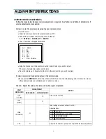
Page 8: ...volume up or down button to enter in the service mode you wish to adjust 2 How to memorize the adjusted values in the service mode Must press DISPLAY button the state which the screen is displaying ea...

Page 9: ...DC bias using internal cross pattern S7 Vertical Size V SIZE 0 127 Align vertical amplitude using internal cross pattern S7 NO SD POWER OFF YES Automatically turn off in 15min for no received signal V...

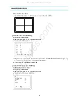
Page 10: ...the screen is changing like this Using the volume up or down button select internal cross pattern Select service adjustment S6 You can see the OSD as shown in below 4 1 Horizontal Position Adjustment...

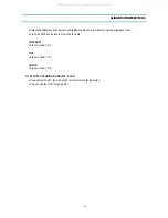
Page 11: ...data of RD GD BD and RB GB BB until a good gray scale with normal whites is obtained ALIGNMENT INSTRUCTIONS Press the DISPLAY button to memorize the data 6 DIGITAL PRESET D P ADJUSTMENTS S9 SUBBRIGHTN...

Page 12: ...ightness level Press the DISPLAY button to memorize the data CONTRAST Fixed value 27 TINT Fixed value 32 COLOR Fixed value 20 7 FACTORY OUTGOING MODE S12 FACT If you select the S12 then the set become...

Page 13: ...reception window of your TV VCR Push buttons of remote control in sequence as follows 1 MUTE INFO MUTE Then the screen will appear as follows Using the channel up or down buttons select S12 FACT Pres...

Page 14: ...0 35 0 36 0 36 3 41 0 37 0 55 0 38 2 81 0 35 39 3 27 0 40 0 0 41 0 0 42 2 52 0 43 4 95 0 5 MODE LOC PIN ON OFF 44 2 73 0 45 1 94 0 46 2 36 0 47 2 44 0 48 4 25 0 51 49 4 25 0 51 50 3 56 0 51 3 04 0 65...

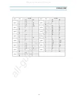
Page 15: ...99 19 0 0 20 0 0 21 0 0 22 0 0 23 NC NC 24 NC NC 25 0 0 MODE LOC PIN ON OFF I701 26 0 0 27 3 81 3 46 28 4 97 4 92 29 4 77 4 71 30 5 04 4 99 31 4 08 0 32 5 04 4 99 33 0 0 34 5 04 4 99 35 0 0 36 0 0 MOD...

Page 16: ...69 0 B 2 31 0 C 5 02 4 99 Q701 E 0 0 B0 0 C 5 02 5 Q702 E 0 0 B0 0 MODE LOC PIN ON OFF C 5 02 5 Q703 E 0 0 B0 0 C 4 93 4 9 Q704 E 4 95 4 92 B 4 32 4 29 C 5 02 4 2 Q707 E 0 21 5 B 0 07 4 9 C 2 89 0 Q7...

Page 17: ...16 WAVEFORMS 1 I101 PIN 19 2 I101 PIN 20 3 I101 PIN 21 4 I101 PIN 23 5 I101 PIN 40 5 I101 PIN 44 7 I101 PIN 46 8 I301 PIN7 All manuals and user guides at all guides com...

Page 18: ...17 WAVEFORMS 9 I701 PIN 7 10 I701 PIN 17 1 I701 PIN 18 12 I801 PIN 2 13 T402 PIN 25 5V 14 T402 PIN 10 5V 15 T402 PIN HEATER 16 T402 PIN 200V All manuals and user guides at all guides com...

Page 19: ...18 WAVEFORMS 17 T401 PIN H V 18 T801 PIN 133V 19 Q403 COLLECT OR 20 CR T SOCKET PIN B 21 CR T SOCKET PIN R 22 CR T SOCKET PIN G All manuals and user guides at all guides com...

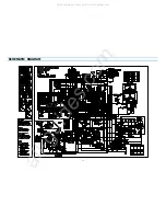
Page 20: ...732 1 A R821 2 C C406 3 B C663 1 A D503 1 C Q404 3 B R442 2 C R733 1 A R822 2 C C408 2 C C701 2 A D504 2 B Q501 2 C R443 2 C R734 1 A R835 3 B C410 2 C C702 2 A D505 1 C Q575 2 B R444 2 C R735 1 A R85...

Page 21: ...20 SCHEMATIC DIAGRAM All manuals and user guides at all guides com a l l g u i d e s c o m...

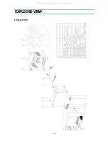
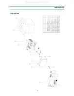
Page 22: ...21 EXPLODED VIEW 1 DTQ 14V1FSN All manuals and user guides at all guides com...

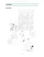
Page 23: ...22 EXPLODED VIEW 2 DTQ 14V3FSN All manuals and user guides at all guides com...

Page 24: ...23 EXPLODED VIEW 3 DTQ 14V5FCN FSN All manuals and user guides at all guides com...

Page 25: ...24 EXPLODED VIEW 4 DTQ 14U1FSN All manuals and user guides at all guides com...

Page 26: ...25 EXPLODED VIEW 5 DTQ 20V1FSN All manuals and user guides at all guides com a l l g u i d e s c o m...

Page 27: ...26 EXPLODED VIEW 6 DTQ 20V3FSN All manuals and user guides at all guides com...

Page 28: ...27 EXPLODED VIEW 7 DTQ 20V4FSN All manuals and user guides at all guides com...

Page 29: ...28 EXPLODED VIEW 8 DTQ 20U1FSN All manuals and user guides at all guides com...

Page 30: ...FLUX SOLDER JS 64T3 40 2291050301 FLUX SOLVENT IM 1000 80 2TP07545CL TAPE OPP 45X50 CLEAR C403 CCYB2H103K C CERA 500V B 0 01MF K C404 CMYH3C722H C MYLAR 1 6KV BUP 7200PF H C406 CMYE2D434J C MYLAR 200V...

Page 31: ...PART NAME DESCRIPTION RE MARK E014 4856310300 EYE LET BSR T0 2 R1 6 E018 4856310300 EYE LET BSR T0 2 R1 6 E019 4856310300 EYE LET BSR T0 2 R1 6 E020 4856310300 EYE LET BSR T0 2 R1 6 E021 4856310600 EY...

Page 32: ...RSS 100MF 6 3X11 TP F801A 4857415001 CLIP FUSE PFC5000 0702 F801B 4857415001 CLIP FUSE PFC5000 0702 L601 58CX430599 COIL CHOKE AZ 9004Y 940K TP LOC PART CODE PART NAME DESCRIPTION RE MARK L805 58CX43...

Page 33: ...AWG22 1 0 65 TIN COATING J017 85801065GY WIRE COPPER AWG22 1 0 65 TIN COATING J018 85801065GY WIRE COPPER AWG22 1 0 65 TIN COATING J019 85801065GY WIRE COPPER AWG22 1 0 65 TIN COATING J020 85801065GY...

Page 34: ...5K OHM J R452 RD 4Z113J R CARBON FILM 1 4 11K OHM J R453 RD AZ103J R CARBON FILM 1 6 10K OHM J LOC PART CODE PART NAME DESCRIPTION RE MARK R501 RD 2Z151J R CARBON FILM 1 2 150 OHM J R502 RD 2Z151J R C...

Page 35: ...FILM 1 6 10K OHM J LOC PART CODE PART NAME DESCRIPTION RE MARK R799 RD AZ103J R CARBON FILM 1 6 10K OHM J R802 RD 4Z205J R CARBON FILM 1 4 2M OHM J R804 RD 4Z201J R CARBON FILM 1 4 200 OHM J R805 RD...

Page 36: ...R CARBON FILM 1 6 1K OHM J 20 R814 RS02Z828JS R M OXIDE FILM 2W 0 82 OHM J SMALL 14 15 R814 RS01Z688J R M OXIDE FILM 1W 0 68 OHM J 20 R821 RD AZ363J R CARBON FILM 1 6 36K OHM J 14 R821 RD AZ273J R CAR...

Page 37: ...DAEWOO ELECTRONICS CO LTD 686 AHYEON DONG MAPO GU SEOUL KOREA C P O BOX 8003 SEOUL KOREA TELEX DWELEC K28177 8 CABLE DAEWOOELEC All manuals and user guides at all guides com...

Page 38: ...1 IC DESCRIPTION U COM I701 X TAL 32 768 KHz Appendix All manuals and user guides at all guides com...

Page 39: ...characters attributes Character colors 16 colors Character background colors 16 colors Fringe shadow colors 16 colors Full screen colors 16 colors Rounding Underline Italic character slanting Attribu...

Page 40: ...9CH CABLE 1 125CH AFT Operation Fine Tuning 2 5Fn 2 5MHz AIR CABLE STD HRC IRC Only Cable 5 6CH is that AFT range is cover over broad band 2 5MHzFn 3 5MHz Memorize Channels If a channel is broadcastin...

Page 41: ...ace I2C Bus Control CH 6 TRAP Function IS 31 PLL IC Band Data Control Byte 2 P3 P0 VHF L 1 VHF H 2 CH6 TRAP 5 IS 31 AIR Cable CH 6 Only UHF 8 5 The Table of Option and Schedule Model Name Pin Option A...

Page 42: ...pin of LA76810 14 Connect this port to AGC of Tuner Default Voltage 3 75V Variable Voltage 3 25V 3 5V 4 0V Use only japan Model This port uses when is Stand By status Condition Input AC Power On Power...

Page 43: ...On Auto Tint High DC 5V Off Use only to control Sound of Stereo mode High DC 5V No Blue Back Low DC 0V Blue Back Low DC 0V Normal High DC 5V Prison Low DC 0V Mono High DC 5V Stereo No Use Low DC 0V T...

Page 44: ...PUT BLUE OUTPUT B AKB INPUT VERTICAL OUTPUT RAMP ALC FILTER HOR BUS VCC HOR AFC FILTER HORIZONTAL OUTPUT AUDIO OUT FM OUTPUT PIF AGC RF AGC OUT PIF INPUT1 PIF INPUT2 IF GND IF VCC FM FILTER AFT OUTPUT...

Page 45: ...8 TROUBLESHOOTING GUIDE 1 NO POWER Appendix All manuals and user guides at all guides com...

Page 46: ...9 TROUBLESHOOTING GUIDE 2 NO PICTURE Check the waveform of I101 46 NG GO to the figure c OK Go the figure d 1701 MICOM Appendix All manuals and user guides at all guides com a l l g u i d e s c o m...

Page 47: ...10 TROUBLESHOOTING GUIDE 3 NO SOUND Check audio output signal of I101 1 NG Go to the figure e OK Go to the figure f g 1701 MICOM Appendix All manuals and user guides at all guides com...
Page 48: ...11 TROUBLESHOOTING GUIDE 4 CH DON T STOP Check the input signal conditions NG Loss of signal or weak signal OK Go to the figure h Appendix All manuals and user guides at all guides com...
Page 49: ...12 TROUBLESHOOTING GUIDE 5 NO COLOR 6 NO VERTICAL DEFLECTION Appendix All manuals and user guides at all guides com...
Page 50: ...13 TROUBLESHOOTING GUIDE 7 NO ON SCREEN DISPLAY 8 REMOTE CONTROL DOES NOT OPERATE Appendix All manuals and user guides at all guides com...
Reviews: