• Safety Check after Servicing
Examine the area surrounding the repaired location for damage or deterioration. Observe that screws, parts and wires
have been returned to original positions. Afterwards, perform the following tests and confirm the specified values in order
to verify compliance with safety standards.
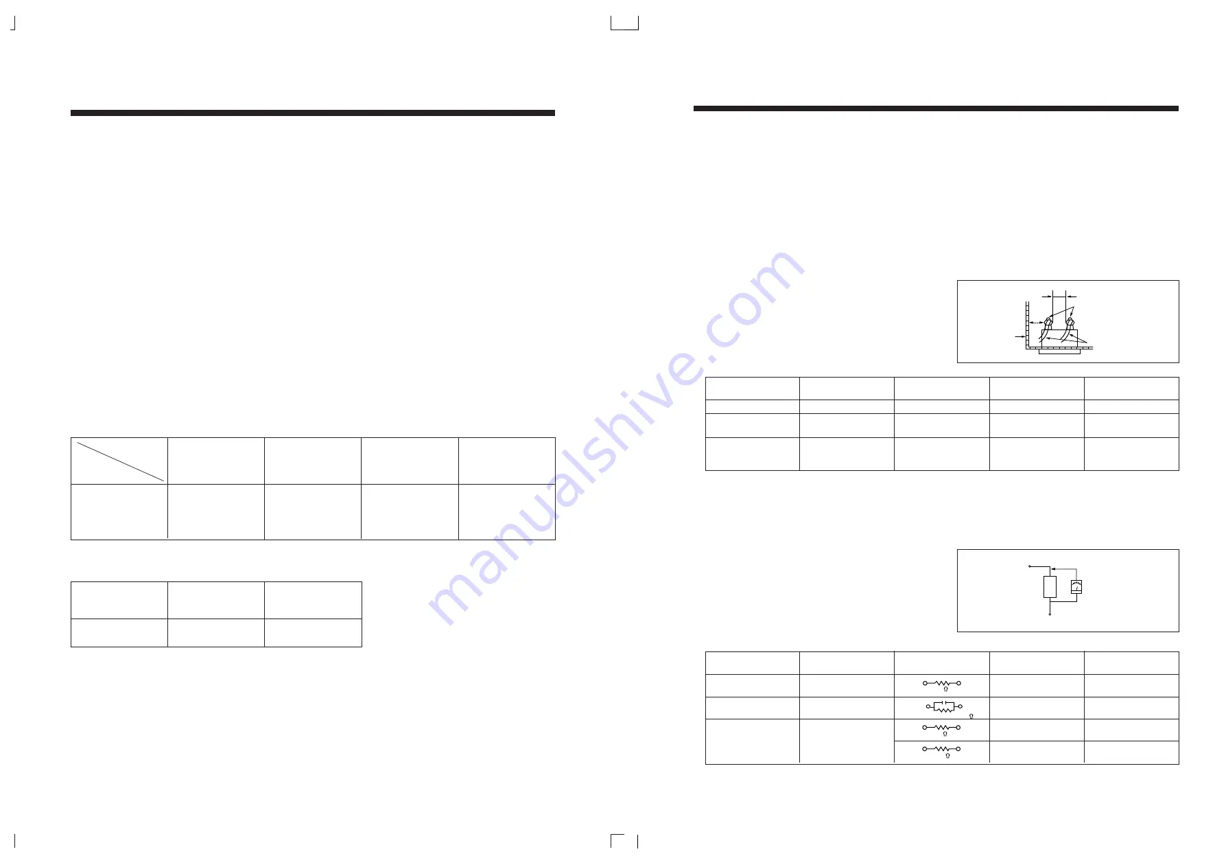
1. Insulation resistance test
Confirm the specified insulation resistance between power cord plug prongs and externally exposed parts of the set
(RF terminals, antenna terminals, video and audio input and output terminals, microphone jacks, earphone jacks, etc.) is
greater than values given in table 1 below.
2. Dielectric strength test
Confirm specified dielectric strength between power cord plug prongs and exposed accessible parts of the set (RF
terminals, antenna terminals, video and audio input and output terminals, microphone jacks, earphone jacks, etc.) is
greater than values given in table 1 below.
3. Clearance distance
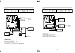
When replacing primary circuit components, confirm
specified clearance distance (d), (d') between soldered
terminals, and between terminals and surrounding
metallic parts. See table below.
Table 1: Rating for selected areas
* Class
II
model only.
Note: This table is unofficial and for reference only. Be sure to confirm the precise values for your particular country and
locality.
4. Leakage current test
Confirm specified or lower leakage current between B (earth ground, power cord plug prongs) and externally exposed
accessible parts (RF terminals, antenna terminals, video and audio input and output terminals, microphone jacks,
earphone jacks, etc.)
Measuring Method: (Power ON)
Insert load Z between B (earth ground, power cord plug
prongs) and exposed accesible parts. Use an AC
voltmeter to measure across both terminals of load Z.
See figure2 and following table.
Table 2: Leakage current ratings for selected areas
Note: This table is unofficial and for reference only. Be sure to confirm the precise values for your particular country and
locality.
Fig. 2
AC Line Voltage
Region
Insulation
Dielectric
Clearance
Resistance
Strength
Distance (d), (d')
100V
Japan
≥
1 M
Ω
/500 V DC
1kV AC 1 minute
≥
3 mm
110 to 130V
USA &
– – –
900V AC 1 minute
≥
3.2mm
Canada
* 110 to 130 V
Europe
≥
4 M
Ω
/500 V DC
3 kV AC 1 minute
≥
3 mm (d)
200 to 240 V
Australia
≥
6 mm (d')
(a: Power cord)
AC Line Voltage
Region
Earth Ground
Load Z
Leakage Current (
i
)
(B) to:
100V
Japan
i
≤
1 m A rms
Exposed accessible
parts
110 to 130 V
USA &
i
≤
0.5 m A rms
Exposed accessible
parts
i
≤
0.7 m A peak
Antenna earth
110 to 130 V
Europe
i
≤
2 m A dc
terminals
200 to 240 V
Australia
i
≤
0.7 m A peak
Other terminals
i
≤
2 m A dc
Fig. 1
1k
1.5k
1.5kµF
2k
50k
d
Primary circuit termimals
Chassis
d'
a
Z
Exposed
accessible
part
AC Voltmter
(high impedance)
Earth Ground
power cord plug prongs
B
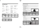
SPECIFICATIONS
SYSTEM
Video signal
PAL standard colour
PAL/SECAM
channel memory
40 positions
UHF output signal
30-39 CH (adjustable)
73±3dBuV
VIDEO
Input: Video Line in
1.0Vp-p
75 ohms unbalanced, sync.
negative
Output: Video line out
75 ohms unbalanced, sync.
negative
Signal to noise ratio
More than 43dB (SP)
Horizontal resolution
230 lines
AUDIO
Input: Audio Line in
Impedance: more than
50Kohm
–8 dBm, unbalanced
Output: Audio line out
Impedance: less than 1Kohm
–6 dBm, unbalanced
Frequency response
100 Hz-8KHz
Signal to noise ratio
More than 38 dB
Audio Distortion
Less than 3% (SP)
TAPE TRANSPORT
Tape width
12.65mm (1/2")
Tape speed
23.39mm/sec
Maximum recording time
180 min, with E-180 tape (EP)
FF. REW time
Approx 4 min (E-180)
GENERAL
Power requirements
AC 230V 50Hz
Power consumption
17W
DIMENSIONS
Set size (WxHxD)
360x90x312 mm
Carton size (WxHxD)
445x180x412 mm
Weight (gross)
5.4Kg
Channel coverage
SYSTEM
PAL,SECAM-B/G
PAL-I/I
PAL,SECAM-B/G
PAL,SECAM-B/G,D/K
WIDE BAND
PAL-I
PAL-B/H
HYPER BAND
VHF Ch 2~12
VHF Ch 2~12
VHF LOW
UHF Ch 21~69
UHF Ch 21~69
Ch 1A~5
Channel
CATV Ch X,Y,Z
CATV Ch X,Y,Z
UHF Ch 21~69
VHF High
SI~S41
SI~S20
Ch 5A~N11
UHF Ch 21~69
IN/OUTPUT JACK TYPE
Model
EUROPE
Asia
South Africa
Australia
JACK
SCART Type
RCA JACK
TYPE
(PHONE JACK)
Summary of Contents for DV-F562 Series
Page 19: ......
Page 20: ...SECTION 5 CIRCUIT DIAGRAM 5 1 CONNECTION DIAGRAM CIRCUIT 33...
Page 21: ...5 2 POWER CIRCUIT 230V ONLY 34...
Page 22: ...5 3 POWER CIRCUIT WIDE RANGE 35 M M M M...
Page 24: ...5 4 SERVO LOGIC CIRCUIT 37 M M...
Page 25: ...5 5 LOGIC CIRCUIT WITH SHUTTLE STATION F542 F342 SERIES 38 1 3 2 1 2 3...
Page 26: ...5 6 LOGIC CIRCUIT F442 F242 F462 F262 F402 1 F202 1 SERIES 39 1 2 3 3 2 1...
Page 27: ...5 7 LOGIC CIRCUIT F562 F362 SERIES 40...
Page 28: ...5 8 LOGIC CIRCUIT F402 2 F202 2 SERIES 41 1 2 3 3 2 1...
Page 29: ......
Page 30: ......
Page 31: ...5 11 PIF CIRCUIT 44 M M M...
Page 32: ......
Page 34: ...5 13 VIDEO CIRCUIT 47...
Page 35: ......
Page 36: ...5 14 OSP CIRCUIT 48 5 15 COLOR CONVERTER 49...
Page 37: ...5 17 IF MODULE CIRCUIT 51 5 16 LINEAR AUDIO CIRCUIT 50 M M M M M M M...
Page 38: ......
Page 39: ...5 19 VPS PDC CIRCUIT AUTO SET 53 5 18 VPS CIRCUIT 52...
Page 40: ...5 21 REMOCON CIRCUIT VR F2BC 55 5 20 REMOCON CIRCUIT VR F3BC 54...
Page 41: ...5 22 REMOCON CIRCUIT VR F2BT 56...
Page 50: ......
Page 51: ......
Page 52: ......


