6
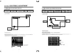
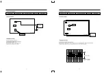
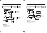
2-2. VIDEO CIRCUIT ADJUSTMENT MENT METHOD
1. EE LEVEL
• Connection Method
• Adjustment Procedure
1) Set the TV/LINE to LINE mode.
2) Supply the Color bar signal with 100% white to the VIDEO IN TERMINAL.
3) Set the VCR to the STOP mode.
4) Connect the oscilloscope to TJ395 and trigger the scope externally with the composite synchronous signal from TJ313
5) Adjust R395 to obtain 0.5 ± 0.02Vp-p between the SYNC TIP and 100% white level.
Adj. Location
Checking Point
Measuring Equipment
Mode
Test Tape
R395
TJ313
Signal Gen, Oscilloscope
–
Color Bar With 100%
TJ395
White
TJ395
R395
TJ313
TOP VIEW
IC301
0.5
+
_ 0.02Vpp
CH-1
OSCILLOSCOPE
CH-2
SIGNAL
GENERATOR
0.5±0.02Vp-p
TJ 395
Horizontal: 10µs/div
vertical : 0.1v/div
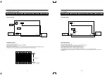
2-1. SERVO CIRCUIT ADJUSTMENT METHOD
1. PLAYBACK PHASE
• Connection Method
• Adjustment Procedure
1) Play back the test tape.(DP-2)
2) Set the oscilloscope to the CHOP mode. Connect CH1 to the SW PULSE (PT01 PIN
3
), and CH2 to the VIDEO OUT
(TJ396) and trigger the scope with signal form CH1
3) Adjust R591 to the positive rising edge of SW PULSE at 6.5H ± 0.5H from the V-SYNC
SECTION 2.
ELECTRICAL ADJUSTMENT
Adj. Location
Checking Point
Measuring Equipment
Mode
Test Tape
TJ396
DP-2
R591
PT01 PIN
3
Oscilloscope
Play
Modulator
TJ396
CH-1
OSCILLOSCOPE
CH-2
R591
PT01
TOP VIEW
6.5H 0.5H
+
_
5
Horizontal: 50µs/div
Vertical: 0.5V/div
6.5±0.5H
Summary of Contents for DV-F562 Series
Page 19: ......
Page 20: ...SECTION 5 CIRCUIT DIAGRAM 5 1 CONNECTION DIAGRAM CIRCUIT 33...
Page 21: ...5 2 POWER CIRCUIT 230V ONLY 34...
Page 22: ...5 3 POWER CIRCUIT WIDE RANGE 35 M M M M...
Page 24: ...5 4 SERVO LOGIC CIRCUIT 37 M M...
Page 25: ...5 5 LOGIC CIRCUIT WITH SHUTTLE STATION F542 F342 SERIES 38 1 3 2 1 2 3...
Page 26: ...5 6 LOGIC CIRCUIT F442 F242 F462 F262 F402 1 F202 1 SERIES 39 1 2 3 3 2 1...
Page 27: ...5 7 LOGIC CIRCUIT F562 F362 SERIES 40...
Page 28: ...5 8 LOGIC CIRCUIT F402 2 F202 2 SERIES 41 1 2 3 3 2 1...
Page 29: ......
Page 30: ......
Page 31: ...5 11 PIF CIRCUIT 44 M M M...
Page 32: ......
Page 34: ...5 13 VIDEO CIRCUIT 47...
Page 35: ......
Page 36: ...5 14 OSP CIRCUIT 48 5 15 COLOR CONVERTER 49...
Page 37: ...5 17 IF MODULE CIRCUIT 51 5 16 LINEAR AUDIO CIRCUIT 50 M M M M M M M...
Page 38: ......
Page 39: ...5 19 VPS PDC CIRCUIT AUTO SET 53 5 18 VPS CIRCUIT 52...
Page 40: ...5 21 REMOCON CIRCUIT VR F2BC 55 5 20 REMOCON CIRCUIT VR F3BC 54...
Page 41: ...5 22 REMOCON CIRCUIT VR F2BT 56...
Page 50: ......
Page 51: ......
Page 52: ......


