9
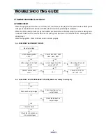
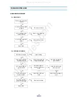
TROUBLE SHOOTING GUIDE
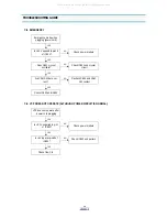
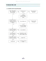
A-3. CHECKING THE DC - INPUT CIRCUIT.
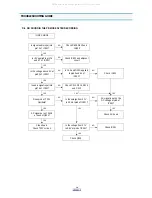
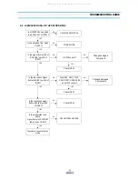
B. LED DISPLAY CIRCUIT.
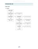
Do not turn on the front
DISPLAY
YES
Check the polarity of
DC adaptor
NO
Change the DC adptor
YES
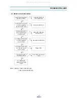
Is Vcc input at pin1 of
IC803?
NO
Check JK801 and pattern
YES
Check SERVO/SYSCON
circuit
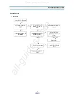
NO
Is 1.25V input at pin4 of
IC803?
NO
Check R805, R806 and
R807
YES
Check SERVO/SYSCON
circuit
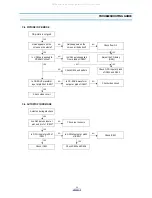
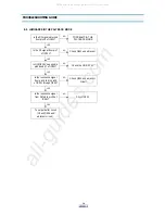
LED does not operate
properly.
NO
Is +5.1V supplied from
D510 cathod to L701?
NO
Check power module
YES
Is +5.1V supplied to the
collectors of Q701~Q706?
NO
Check L701
YES
Are the signals supplied
from u-com to the bases
of Q701~Q706?
NO
Check u-com
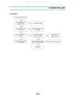
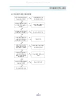
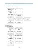
YES
Are the signals supplied
from u-com to the bases
of Q707~Q713?
NO
Check u-com
YES
Are the signals supplied
To the LED(G701)?
NO
Check Q701~ Q713 and
patterns
YES
Check G701 and pattern
All manuals and user guides at all-guides.com
Summary of Contents for DV-S103A Series
Page 33: ...32 PRINTED CIRCUIT BOARD 1 PCB MAIN All manuals and user guides at all guides com...
Page 34: ...33 PRINTED CIRCUIT BOARD 2 PCB POWER SMPS All manuals and user guides at all guides com...
Page 40: ...39 EXPLODING VIEWS PARTS LIST 1 PACKING AS All manuals and user guides at all guides com...


