24
TROUBLE SHOOTING GUIDE
E-7.
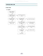
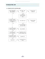
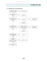
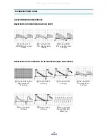
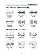
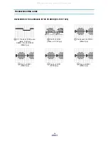
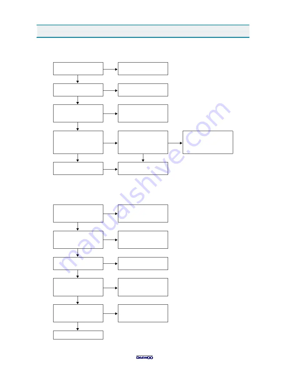
COLOUR SIGNAL IN THE RECORD MODE
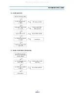
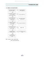
F. MODULATOR CIRCUIT
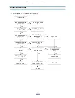
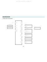
F-1. NO MODULATOR OUTPUT
Is ON/OFF 5V supplied to
pin36 and 47 of IC301?
NO
Check the ON/OFF 5V
YES
Is the obtained from pin34
of IC301?
NO
TO EE MODE
YES
Is the colour signal from
pin50 of IC301 to pin52
of IC301?
NO
Check IC302, PCB .and
adjacent circuit
YES
Is the down converted
colour signal from pin14
of IC301 fed to pin10 of
IC401 through C406?
NO
Check IC302, PCB and
adjacent circuit
NO
Changed damaged
components
YES
YES
TO PREAMP CIRCUIT
IN THE REC MODE
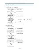
NO
Check IC301
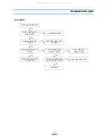
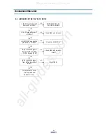
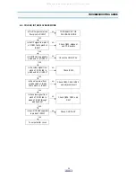
Check the output channel
of VCP and input
channel of TV?
NO
Set the output channel of
VCP reference to owners
Mannual
YES
Are +5V & ON/OFF 5V
applied to pin1 and 4 of
RF101?
NO
Check ON/OFF 5V and
the option circuit
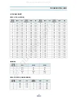
according to the option table
YES
Is ON/OFF 12V applied to
pin7 of RF101?
NO
Check RJ013 and IC801
YES
Are video and audio signal
input into pin2 and 6 of
RF101?
NO
Check A/V circuit
YES
Are CLK & DATA signal
input into pin3 and 5 of
RF101?
NO
Check SERVO/SYSCON
circuit
YES
Check RF101
All manuals and user guides at all-guides.com
Summary of Contents for DV-S103A Series
Page 33: ...32 PRINTED CIRCUIT BOARD 1 PCB MAIN All manuals and user guides at all guides com...
Page 34: ...33 PRINTED CIRCUIT BOARD 2 PCB POWER SMPS All manuals and user guides at all guides com...
Page 40: ...39 EXPLODING VIEWS PARTS LIST 1 PACKING AS All manuals and user guides at all guides com...

