21
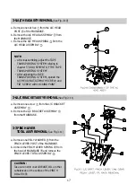
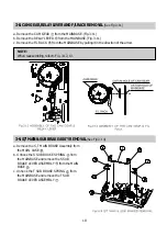
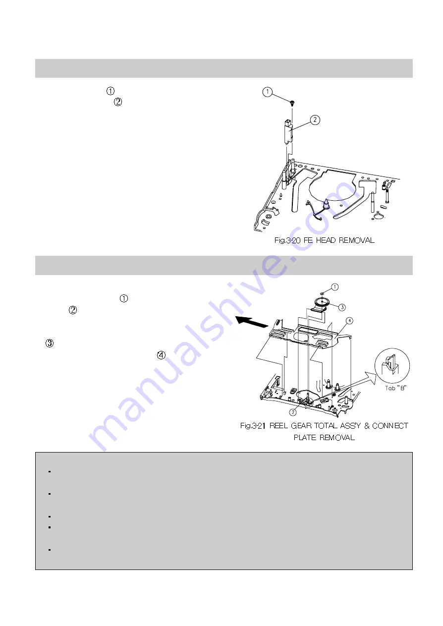
3-13. FE HEAD REMOVAL
(See Fig.3-20)
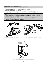
3-14. REEL GEAR TOTAL ASS'Y & CONNECT PLATE REMOVAL
(Fig.3-21)
Remove one screw
fixing the FE HEAD and
remove the FE HEAD
from the MAINBASE.
a. Turn over the DECK MECHANISM and remove
one POLY WASHER
from the REEL GEAR
POST .
b. After separating tab 'B' of the MAINBASE,
remove the REEL GEAR TOTAL ASSEMBLY
from the MAINBASE.
c. Remove the CONNECT PLATE
from the
MAINBASE by pushing it in the direction of the
arrow.
NOTE:
When removing the CONNECT PLATE with the F/L RACK installed, take care not to damage or
bend the CONNECT PLATE.
After assembling or disassembling the REEL GEAR TOTAL ASSEMBLY, take care not to get OIL,
GREASE or other substances on the REEL BELT.
Take care not to deform or break tab "B".
Check the assembly state & the operating state of the REEL GEAR TOTAL ASSEMBLY befor
assembling.
After reassembling, check the FF, REW, PLAY and REVIEW MODES and the existence of noise
when operating the MODES.
Summary of Contents for GB14H3
Page 5: ...4 CIRCUIT BLOCK DIAGRAM ...
Page 12: ... 11 SCHEMATIC DIAGRAM ...
Page 13: ... 12 SCHEMATIC DIAGRAM ...
Page 14: ...13 EXPLODED VIEW 1 14H3 ...
Page 15: ...14 EXPLODED VIEW 2 14H4 ...
Page 16: ...15 EXPLODED VIEW 3 20H3 ...
Page 17: ...16 EXPLODED VIEW 4 20H4 ...
Page 18: ...17 EXPLODED VIEW 5 21H4 ...
Page 19: ......
Page 20: ......
Page 58: ...3 1 2 1 WIRE DIAGRAM 1 2WIREDIAGRAM ...
Page 62: ...7 2 1 2 PARTS LOCATION OF FRONT LOADING ASS Y A TOP VIEW B FRONT VIEW ...
Page 92: ...37 6 EXPLODEDVIEWANDPARTSLIST 6 1 EXPLODEDVIEWOFDECKASS Y TOPVIEW ...
Page 93: ...38 6 2 EXPLODEDVIEWOFDECKASS Y BOTTOMVIEW ...
Page 94: ...39 6 3 EXPLODEDVIEWOFF LASS Y ...
Page 95: ...40 ...


