7
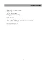
7-2. AUTO PG ADJUSTMENT
1) After adjustment of 7-1. Press the “REC.” button.
2) Eject the Test tape.
7-3. AZIMUTH ADJUSTMENT
1) Adjust point : AZIMUTH SCREW
Checking point : SOUND OUTPUT (P601)
Measuring Equipment : oscilloscope or audio level meter.
Mode : PLAYBACK
Test tape : DP-2 (6KHz)
* Adjustment Procedure
1) Connect the measuring equipment to the AUDIO OUTPUT (P601) terminal.
2) After test tape playback, adjust the output level maximally by varing the azimuth screw.
3) Fix the azimuth screw with locking paint.
* If EEPROM (I702) has been changed :
- Option data has to be changed and
- all alignment function has to be readjusted.
ALIGNMENT INSTRUCTIONS
Summary of Contents for GB14H3
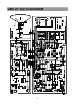
Page 5: ...4 CIRCUIT BLOCK DIAGRAM ...
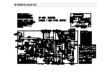
Page 12: ... 11 SCHEMATIC DIAGRAM ...
Page 13: ... 12 SCHEMATIC DIAGRAM ...
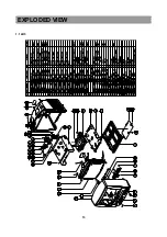
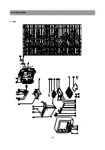
Page 14: ...13 EXPLODED VIEW 1 14H3 ...
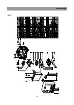
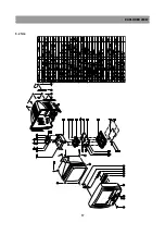
Page 15: ...14 EXPLODED VIEW 2 14H4 ...
Page 16: ...15 EXPLODED VIEW 3 20H3 ...
Page 17: ...16 EXPLODED VIEW 4 20H4 ...
Page 18: ...17 EXPLODED VIEW 5 21H4 ...
Page 19: ......
Page 20: ......
Page 58: ...3 1 2 1 WIRE DIAGRAM 1 2WIREDIAGRAM ...
Page 62: ...7 2 1 2 PARTS LOCATION OF FRONT LOADING ASS Y A TOP VIEW B FRONT VIEW ...
Page 92: ...37 6 EXPLODEDVIEWANDPARTSLIST 6 1 EXPLODEDVIEWOFDECKASS Y TOPVIEW ...
Page 93: ...38 6 2 EXPLODEDVIEWOFDECKASS Y BOTTOMVIEW ...
Page 94: ...39 6 3 EXPLODEDVIEWOFF LASS Y ...
Page 95: ...40 ...


