26
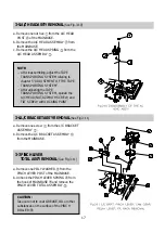
4-3. MECHANICAL MODE (OPERATING THE VCRWITHOUT A CASSETTE TAPE)
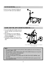
a. Remove the FRONT LOADING MECHANISM from the DECK MECHANISM.
b. Pull the F/L RACK.
c. The S/T POLE BASES are loaded and PLAY BACK MODE starts.
d. Turn off the power when the MECHANISM is in the desired position.
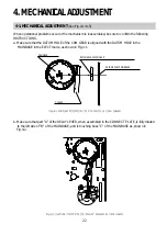
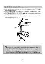
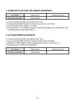
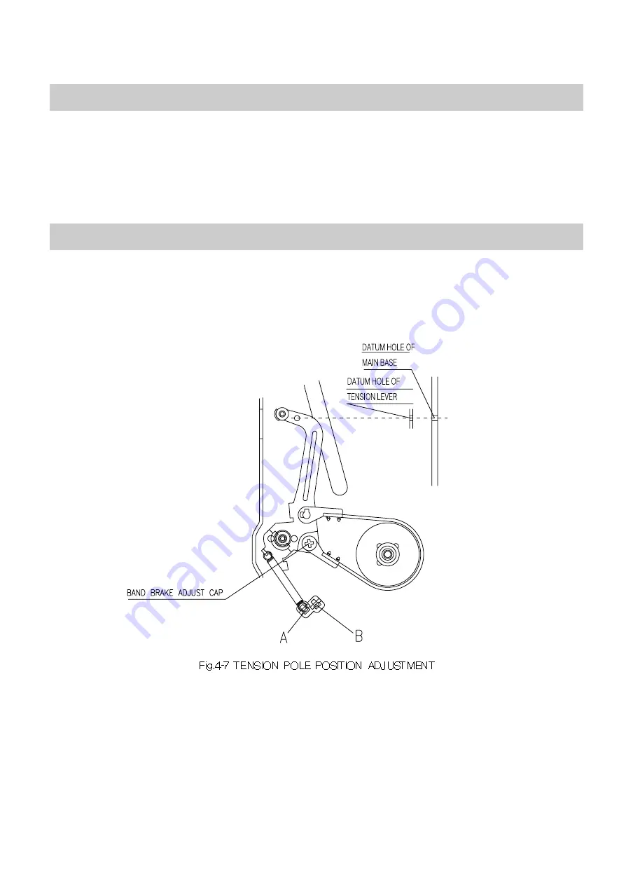
a. MAKE MECHANICAL MODE be PLAY MODE. Refer to "4-3 MECHANICAL MODE".
b. Confirm that the datum hole of TENSION LEVER is aligned with the datum hole of the MAIN BASE.
c. If requirement "b" is not satisfied, turn the BAND BRAKE ADJUST CAP clockwise or counter-clockwise
until the two datum hole are aligned with each other.
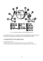
4-4. TENSION POLE POSITION ADJUSTMENT
Summary of Contents for GB14H3
Page 5: ...4 CIRCUIT BLOCK DIAGRAM ...
Page 12: ... 11 SCHEMATIC DIAGRAM ...
Page 13: ... 12 SCHEMATIC DIAGRAM ...
Page 14: ...13 EXPLODED VIEW 1 14H3 ...
Page 15: ...14 EXPLODED VIEW 2 14H4 ...
Page 16: ...15 EXPLODED VIEW 3 20H3 ...
Page 17: ...16 EXPLODED VIEW 4 20H4 ...
Page 18: ...17 EXPLODED VIEW 5 21H4 ...
Page 19: ......
Page 20: ......
Page 58: ...3 1 2 1 WIRE DIAGRAM 1 2WIREDIAGRAM ...
Page 62: ...7 2 1 2 PARTS LOCATION OF FRONT LOADING ASS Y A TOP VIEW B FRONT VIEW ...
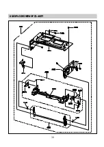
Page 92: ...37 6 EXPLODEDVIEWANDPARTSLIST 6 1 EXPLODEDVIEWOFDECKASS Y TOPVIEW ...
Page 93: ...38 6 2 EXPLODEDVIEWOFDECKASS Y BOTTOMVIEW ...
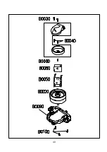
Page 94: ...39 6 3 EXPLODEDVIEWOFF LASS Y ...
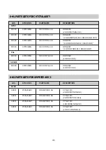
Page 95: ...40 ...


