background image

13

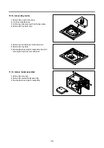
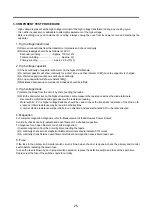
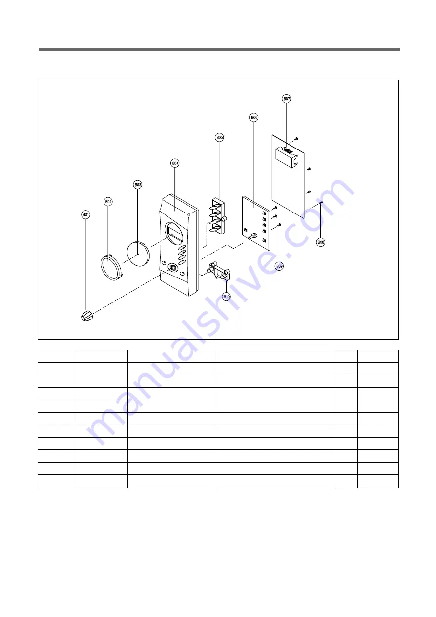
5. To remove control panel parts. 

1) Remove the screw which secure the control panel, push up two snap fits and draw forward the control panel assembly.
2) Remove screws which secure the PCB assembly to control panel.
3) Disconnect wire flat from the connector of the PCB assembly.
4) Remove the PCB from the control panel.
5) Remove the function buttons knob, window display and decorator ring from the control panel.
6) Reverse the above steps for reassembly.

13

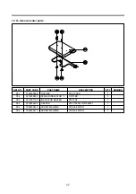
REF NO.

PART CODE

PART NAME

DESCRIPTION

Q'TY

REMARK

B01

3513408010

KNOB VOLUME

ABS SG-175 SG-0760D COATING

1

B02

3511613210

DECORATOR RING

ABS SG-175 SG-0760D COATING

1

B03

3515502200

WINDOW DISPLAY

SAN CR-5381 SMOG

1

B04

3516731310

CONTROL-PANEL

HIPS SG-970 HG-1760H

1

B05

3516912510

BUTTON FUNCTION-A

ABS SG-175 SG-0760D COATING

1

B06

PKBPMSAZ00

PCB BUTTON MANUAL AS KOR-6C6R5S

1

B07 PKMPMSAZ30 PCB MAIN MANUAL AS KOG-3C6R 1

B08

7122401211

SCREW TAPPING

T2S TRS 4X12 MFZN

4

B09

7621301011

SCREW TAPPING

T2 PAN 3X10 PW MFZN

3

B10

3516912610

BUTTON FUNCTION-B

ABS SG-175 SG-0760D COATING

1

C/PANEL ASSEMBLY : PKCPSWAZ30

Summary of Contents for KOG-3C6R

Page 1: ...C6R5S001 http svc dwe co kr Jan 2004 Caution In this Manual some parts can be changed for improving their performance without notice in the parts list So if you need the latest parts information please refer to PPL Parts Price List in Service Information Center http svc dwe co kr ...

Page 2: ...ck monitor door seal and microwave generation and transmission systems shall be repaired replaced or adjusted by procedures described in this manual before the oven is released to the owner e A microwave leakage check to verify compliance with the Federal performance standard should be per formed on each oven prior to release to the owner TABLE OF CONTENTS SAFETY AND PRECAUTIONS 2 1 FOR SAFE OPERA...

Page 3: ...ed oven unit is found to servicing a microwave emission check should be performed prior to servicing the oven a inform the manufacturer importer or assembler b repair the unit at no cost to the owner c attempt to ascertain the cause of the excessive leakage d tell the owner of the unit not to use the unit until the oven has been brought into compliance 3 If the oven operates with the door open the...

Page 4: ...ATION 2200 W MICROWAVE ENERGY OUTPUT 800W MICROWAVE FREQUENCY 2450MHz OUTSIDE DIMENSIONS WXHXD 465X279X384mm CAVITY DIMENSIONS WXHXD 290X220X306mm NET WEIGHT APPROX 13 7Kg TIMER 60 min 00 sec POWER SELECTIONS 5 LEVELS CAVITY VOLUME 0 7 Cu Ft Specifications are subject to change without notice SPECIFICATIONS ...

Page 5: ...4 EXTERNAL VIEW 1 OUTER DIMENSION 465 384 ...

Page 6: ... is to remain in the oven for all cooking 8 8 Roller guide This must always be used for cooking together with the glass cooking tray 9 9 Glass cooking tray Made of special heat resistant glass Food in a proper receptacle is placed on this tray for cooking 0 0 Door viewing screen Allows viewing of food The screen is designed so that light can pass through but not the microwave q q Door hook When th...

Page 7: ...t 3 3 MICRO Def Used to set power level Used to defrost foods by weight or time 4 4 Grill Combi Used to cook grill combi 5 5 Clock Used to set clock 6 6 Start Express cook Used to start the oven operation and also increase the reheat time by 30 seconds 7 7 Dial knob Used to set the time and weight 8 8 Stop Clear Used to stop the oven operation or to erase all entries ...

Page 8: ...st be repaired with cable of same type Such a cable can be purchased from DAEWOO and must be installed by a qualified person 6 Examine the oven after unpacking for any damage such as A misaligned door broken door or a dent in cavity If any of the above are visible DO NOT INSTALL and notify dealer immediately 7 Do not operate the oven if it is colder than room temperature This may occur during deli...

Page 9: ...re If the oven door is opened during the oven operation all information is retained 10 If the START button is pressed and the oven does not operate check the area between the door and make sure the 11 When using the GRILL or COMBI mode Do not open the door so often the temperature inside the oven decrease and the cooking may not complete in setting time Never touch the oven window and metal interi...

Page 10: ...ir work 2 Warning about the electric charge in the high voltage capacitor For about 30 seconds after the operation stopped and electric charge remains in the high voltage capacitor When replacing or checking parts short between oven chassis and the negative high terminal of the high voltage capacitor by using a properly insulated screwdriver to discharge 4 When the 12A fuse is blown out due to the...

Page 11: ...ward 2 To remove door assembly 1 Remove a screw which secure the stopper hinge top 2 Remove the door assembly from top plate of cavity 3 Reverse the above for reassembly NOTE After replacing the door assembly perform a check of correct alignment with the hinge and cavity front plate 10 ...

Page 12: ...700 HOOK POM 1 A08 3515101320 SPRING HOOK HSW 3 1 A09 7122401211 SCREW TAPPING T2S TRS 4X12 MFZN 2 A10 3512605110 HANDLE DOOR ABS SG 175 SG 0760D SPRAY 1 3 To remove door parts 1 Remove the gasket door from door weld as 2 Remove the gasket door from door weld as 3 Remove the door frame from door weld as 4 Remove the stopper hinge top from door weld as 5 Remove the spring and the hook 6 Remove the ...

Page 13: ...ge top and then push the door to contact the door seal to oven front surface Tighten a screw 2 To reduce gap located on part B Loosen two screws on stopper hinge under and then push the door to contact the door seal to oven front surface Tighten two screws NOTE A small gap may be acceptable if the microwave leakage does not exceed 4mW cm2 12 ...

Page 14: ... for reassembly 13 REF NO PART CODE PART NAME DESCRIPTION Q TY REMARK B01 3513408010 KNOB VOLUME ABS SG 175 SG 0760D COATING 1 B02 3511613210 DECORATOR RING ABS SG 175 SG 0760D COATING 1 B03 3515502200 WINDOW DISPLAY SAN CR 5381 SMOG 1 B04 3516731310 CONTROL PANEL HIPS SG 970 HG 1760H 1 B05 3516912510 BUTTON FUNCTION A ABS SG 175 SG 0760D COATING 1 B06 PKBPMSAZ00 PCB BUTTON MANUAL AS KOR 6C6R5S 1 ...

Page 15: ...e circuit wiring 7 To remove magnetron 1 Remove a screw which secure the magnetron 2 Remove the magnetron 3 Reverse the above steps for reassembly NOTE Never install the magnetron without the metallic gasket plate which is packed with each magnetron to pre vent microwave leakage Whenever repair work is carried out on magnetron check the microwave leakage It shall not exceed 4mW cm2 for a fully ass...

Page 16: ...assembly 3 Pull the fan from the motor shaft 4 Remove two screws which secure the motor shaded pole 5 Remove the motor shaded pole 6 Reverse the above steps for reassembly 9 To remove H V transformer 1 Remove four screws holding the H V transformer 2 Remove the H V transformer 3 Reverse the above steps for reassembly 15 ...

Page 17: ...se plate 4 Remove the tray motor cover 5 Remove a screw which secure the tray motor 6 Remove the tray motor 7 Reverse the above steps for reassembly except for securing the tray motor cover with screw 11 To remove heater assembly 1 Remove the three nuts 2 Remove the insulator heater assembly 3 Reverse the above steps for reassembly ...

Page 18: ...8 NUT HEX 6N 2 5 SUS 1 C02 3515000600 SPACER INSULATOR I C3771BD 1 C03 3513301100 INSULATOR HEATER SPP T0 8 1 C04 3512803400 HEATER 230V 1000W 1R67994001 1 C05 7002500613 SCREW MACHINE TRS 5X6 MFCR 1 C06 7002400413 SCREW MACHINE TRS 4X4 MFCR 1 12 To remove heater parts ...

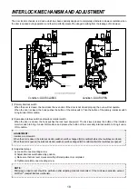
Page 19: ...er downward The lock lever presses the button of the interlock monitor switch to bring it under NO condition and presses the button of the secondary interlock switch to bring it under ON condition 3 Adjustment steps a Loosen the one mounting screw b Adjust interlock switch assembly position c Make sure that lock lever moves smoothly after adjustment is completed d Tighten completely one mounting s...

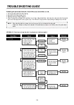
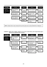
Page 20: ...t with door partially open until interlock moni tor switch contact close COM NO Replace NOTE Shorted contacts of primary interlock switch Shorted contacts of primary interlock switch Defective low volt age transformer Defective high voltage transformer Replace Following the procedure below to check if the oven is defective or not 1 Check grounding before trouble checking 2 Be careful of the high v...

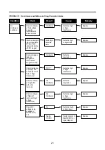
Page 21: ...n on Check continuity of primary interlock switch No Continuity Malfunction of primary interlock switch Adjust or Replace Malfunction of sec ondary interlock and D O M switch Check continuity of secondary interlock and D O M switchs No Continuity Replace Defective touch con trol circuit Check D C voltage being supplied to RELAY RY2 coil 0V Replace Faulty contacts of RELAY RY2 or open relay coil Ap...

Page 22: ...diode Replace Connect megger leads to magnetron terminal and magnetron body Continuity Defective magnetron Replace Check resistance of primary and secondary coil of high voltage transformer Defective high voltage transformer Replace Check continuity of magnetron with wires removed No Continuity Defective magnetron Replace Check continuity of filament terminal of high voltage transformer No Continu...

Page 23: ...normally but no display shows 8 Display obviously jumps in time while counting down 9 Display counts down noticeably too fast while cooking 10 Display does not show the time of day when STOP CLEAR button is pressed 11 Oven lamp and turntable motor do not stop although cooking is finished Check if the RELAY 2 contacts close If they are close replace touch control circuit Condition Check Result Caus...

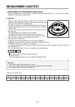
Page 24: ...ssel the load is immediately placed on the center of the shelf which is in the lowest normal position 4 Microwave power is switched on 5 Heating time should be exactly A seconds Refer to table as following Heating time is measured while the microwave generator is operating at full power The filament heat up time for magnetron is not included 6 The initial and final temperature of water is selected...

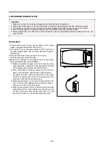
Page 25: ...et door seem door viewing screen the exhaust air vents and the suction air vents 3 Measuring should be in a counter clockwise direction at a rate of 1 in sec If the leakage of the cabinet door seem is unknown move the probe more slowly 4 When measuring near a corner of the door keep the probe perpendicular to the areas making sure the probe end at the base of the cone does not get closer than 2 in...

Page 26: ...ohmmeter set on the highest resistance scale measure the resistance across the diode terminals Reverse the meter leads and again observe the resistance reading Meter with 6V 9V or higher voltage batteries should be used to check the front back resistance of the diode oth erwise an infinite resistance may be read in both directions A normal diode s resistance will be infinite in one direction and s...

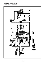
Page 27: ...26 WIRING DIAGRAM ...

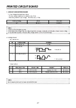
Page 28: ...E Each measure point must be measured with GND points NOTE 1 Refer to Circuit Diagram point 4 2 Secondary side voltage of the low voltage transformer changes in proportion to fluctuation of power source voltage 3 The allowable tolerance of the secondary voltage is within 5 of nominal voltage T 5V 0V T 250 ns 4MHz T Terminal Voltage 4 7 LOAD DC 12 V NO LOAD AC 29 5 V NO MEASURE POINT WAVE FORM REME...

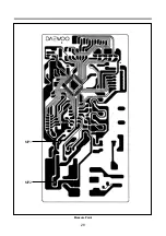
Page 29: ...28 MP1 MP2 Measure Point ...

Page 30: ...r is opened during operation the count down timer does not stop refer to Circuit Diagram Point 1 Check method 6 When the digital clock does not operate properly refer to Circuit Diagram Point 5 If clock does not keep exact time you must check resistor R17 18 transistor Q11 STATE POINT RELAY 2 ON 5VDC GND RELAY 2 OFF GND 12VDC STATE POINT RELAY 1 ON 5VDC GND RELAY 1 OFF GND 12VDC STATE POINT 1 DOOR...

Page 31: ...30 2 PCB CIRCUIT DIAGRAM ...

Page 32: ...LM R10 12 18 RD AZ103J 1 6 10K OHM 5 3 21 R CARBON FILM R17 RD AZ473J 1 6 47K OHM 5 1 22 R CARBON FILM R15 RD AZ105J 1 6 1M OHM 5 1 23 R CARBON FILM R19 RD 4Z510J 1 4 51 OHM 5 SMALL 1 24 RESONATOR CERA CR1 5P4R00MTS CRT4 00MS 1 25 SW RELAY RY1 RY3 5SC0101121 G5G 1A 1C 1P DC12V 2 26 SW RELAY RY2 5SC0101128 CS11 12SH 1C 1P 1 27 TR Q1 Q5 TZRA106M KRA 106M AUTO 5 28 TR Q8 Q12 TZRC106M KRC 106M AUTO 5 ...

Page 33: ...32 1 DOOR ASSEMBLY Refer to Disassembly and assembly 2 CONTROL PANEL ASSEMBLY Refer to Disassembly and assembly 3 TOTAL ASSEMBLY EXPLODED VIEW AND PARTS LIST ...

Page 34: ...CITOR SECC T0 6 1 F22 3518302200 CAPACITOR HV 2100VAC 0 98UF 187 1 F23 3518400900 DIODE HV AS HVR 1X 30B 187 1 F24 3518701100 FUSE HV 5KV 0 55A HV 41A55 02 1 F25 3518119880 TRANS HV R1S580 EA00 1 F26 3516003700 SPECIAL SCREW TT3 HEX 4X8 FLG MFZN 4 F27 3510311700 BASE SBHG T0 7 1 F28 7112401011 SCREW TAPPING T1 TRS 4 10 MFZN 5 F29 3512100900 FOOT PP DASF 130 2 F30 7272400811 SCREW TAPTITE TT3 TRS 4...

Reviews: