background image

29

Time Lapse Video Cassette Recorder

28

Time Lapse Video Cassette Recorder

Special Playback

Digital Shuttle

1

To use this function with remote control

• Press DIGITAL S/- button on remote

control in playback mode to enter into Digital
Shuttle function.

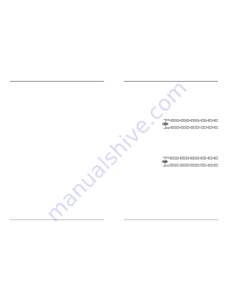
• Shuttle speed will change as follows :

2

To use this function with set button

• Press STILL button on front panel in playback

mode. Then press REW or FF button to enter into
Shuttle function.

• You can’t use shuttle

function in front panel
button without pressing
STILL button first.

• To use this function with

digital shuttle press STILL
button on the remote
control in playback mode.

• Shuttle speed will change as follows :

3

To return to normal playback, press the PLAY button.

4

Slow & Reverse slow speed
Slow step 1 = 1/30 times
Slow step 2 = 1/15 times
Slow step 3 = 1/5 times
Reverse slow step 1 = -1/30 times
Reverse slow step 2 = -1/15 times
Reverse slow step 3 = -1/5 times

Audio Playback

Audio playback is only possible in 2-hour, 6-hour, 18-
hour and 30-hour modes.
The playback speed has to be the same as the recording
speed, for normal playback of the audio.
For a tape recorded in 2-hour, 6-hour 18-hour and 30-
hour modes,to playback the audio, press the AUDIO ON
button after pressing the PLAY button. “A” will be
displayed to the left of the playback speed on the display
panel. Press the AUDIO ON button again to remove “A”.

• Noise will appear in the

image when audio
playback is  used in 18-
hour or 30-hour mode.

Summary of Contents for 82-10765

Page 1: ...E 960 HOUR TIME LAPSE RECORDER User s Guide TVD 960N EJECT REC Be sure to read carefully and follow all the SAFETY INFORMATION on pages i ii iii Keep the manual in a safe place for future reference P...

Page 2: ...at will help to assure your enjoyment and proper use of the video product and accessory equipment Please read them carefully before operating and using your video product Installation 1 Read and Follo...

Page 3: ...ler or local power company For video products intended to operate from battery power or other sources refer to the operating instructions 6 Overloading Do not overload wall outlets of extension cords...

Page 4: ...ntrol 5 Connections 6 Video Cassettes Tapes 7 Types of On screen displays and Display Sequence 8 Setting the Clock 10 Changing the On Screen Display 12 Normal Recording 14 Program Timer Recording 16 A...

Page 5: ...splay eg E Error 04 Error No E 01 The cassette cannot be loaded or unloaded E 02 The tape stops E 03 The drum can not rotate properly E 04 The tape is cut broken E 05 The DEW Sensor Error AUDIO ON dis...

Page 6: ...on 21 REVERSE PLAY button 22 REC button 23 REC PLAY SPEED button 24 REC CHECK button 25 MENU button 4 Time Lapse Video Cassette Recorder Back Panel 1 ALARM 2 ALARM Input terminal 2 ALARM 3 ALARM Input...

Page 7: ...re below NOTE Make sure to turn the power off on all devices before making the connections Power Cord Installation Insert the plug of the power cord into an outlet Adaptor Installation For more detail...

Page 8: ...ed and the normal screen is displayed During recording or playback the menus cannot be displayed Press the MENU button First time Press the SHIFT button to move the arrow mark downward for the desired...

Page 9: ...cassette tapes It is recommended to use T 120 VHS or T 160 VHS video cassette tapes for optimal performance Handling Cassette Tapes Cassette tapes should always be stored vertically in their cases awa...

Page 10: ...ess the SHIFT button until the arrow mark points Display set 5 Press the SHIFT button to select Display Set then the DISPLAY SET menu is displayed 6 Press the SET or button to set the minutes eg 30 th...

Page 11: ...2 SP 2 67 1 60 Sec 60 6 EP 8 1 60 Sec 60 YES Continuous 18 EP 24 3 60 Sec 20 30 EP 40 5 60 Sec 12 48 SP 64 24 60 Sec 2 5 72 SP 96 0 6 1 67 96 SP 128 0 8 1 25 120 SP 160 1 0 1 168 SP 224 1 4 0 71 NO In...

Page 12: ...rt hour position 6 Press the SET or button to set the recording start hour eg 10 then press the SHIFT button The cursor is moved to the recording start minutes position 7 Press the SET or button to se...

Page 13: ...eg 00 then press the SHIFT button 10 Press the SET or button to select the recording speed eg 18 then press the SHIFT button The cursor is moved to the N Y position 11 Press the SET or button to selec...

Page 14: ...ower is restored within the recording set duration alarm recording will continue When you select Alarm Duration as 20sec 30sec 40sec or 1min alarm search error may happen Therefore confirm it in Alarm...

Page 15: ...minute T END Records until the tape end is reached when there is alarm trigger input Alarm Recording Counter Display During alarm recording will be flashing on the display panel The maximum display nu...

Page 16: ...ecording will not be possible Series Recording Using 2 VCRs or more the series recording function lets you switch recording from one unit to the next only with VCRs of the same model as this one Serie...

Page 17: ...the vertical rolling of the image 2 If it cannot be corrected press the TRACKING button A slow motion effect or accelerated playback effect can be achieved by using a slower or faster playback speed...

Page 18: ...ayback mode Shuttle speed will change as follows 3 To return to normal playback press the PLAY button 4 Slow Reverse slow speed Slow step 1 1 30 times Slow step 2 1 15 times Slow step 3 1 5 times Reve...

Page 19: ...ck mode to enter into Reverse Play mode To return to normal playback press the PLAY button Picture Search 1 Press the FF CUE or REW REVIEW button during normal playback The image can be seen while the...

Page 20: ...ase indication In 18 hour recording mode each second of the tape counter actually represents approximately 18 6 3 real seconds In the other EP recording speed modes 30H the tape counter indication is...

Page 21: ...external equipment the field will be switched automatically FIELD 1 pulse is output after each set number of fields VHS mode 2H 6H FRAME 1 pulse is output after each set number frames VHS mode 2H 6H...

Page 22: ...isplayed The data for the previous alarm recordings past 35 is erased POWER LOSS the number of power losses and the date and time of the 35 most recent power losses and recoveries are displayed Settin...

Page 23: ...ring recording when the end of the tape is reached the output becomes DC 5V 2 Low During recording when the end of the tape is reached the output becomes DC 0V ALARM INPUT Terminal This terminal is to...

Page 24: ...camera switching unit or a quad compressor 1 Low 2 High SERIES OUTPUT Terminal During recording when the end of the tape is reached the output becomes DC 5V SERIES INPUT Terminal If the input becomes...

Page 25: ...on the TV monitor is correct 3 Check that the on screen display of the date and time is correct 4 Press the REW button to rewind the recorded tape a few seconds 5 Press the PLAY button and check that...

Page 26: ...POWER key E 05 Error at DEW Sensor happens Refer to DEW Sensor Troubleshooting Guide If the unit does not operate normally when you follow the instructions indicated in the manual please refer to the...

Page 27: ...tput DC 4 5V H DC 0 0 8V L 1k Warning output DC 4 5V H DC 0 0 8V L 1k Series input DC 4 5V H DC 0 0 8V L 5 7k Series output DC 4 5V H DC 0 0 8V L 1k Switch output DC 4 5V H DC 0 0 8V L 1k Common 0V GN...

Page 28: ...aced or changed This warranty is in lieu of all warranties expressed or implied and no representative or person is authorized to assume for us any other liability in connection with the sale of our el...

Reviews: