background image

- 4 -

Adjustments

1. TAPE SECTION

Test Tape be used

HEAD ADJUSTMENT (AZIMUTH)

1.  10KHz test tape(example: MTT-114N) must be used for this adjustment.

2.  Connect to VTVM or oscilloscope to the headphone jack or speaker terminal.

3.  Press the play button.

4.  Adjust the azimuth by using a screw driver to maintain the max. L&R output voltage.

5.  Adjust tape A(1), tape B(2) respectively, Please secure the azimuth position by using locking paint.

RECORDING BIAS OSCILLATOR FREQUENCY ADJUSTMENT

1.  Connect the frequency counter to TP603, GND.

2.  Press the REC button.

3.  Adjust L603 to obtain 80 KHz

±

100Hz

Tape

Contents

 Use

MTT-111N

3 KHz

Tape Speed Adjustment

MTT-114N

10 KHz

Head Azimuth Adjustment

MTT-5511

Blank

Record Frequency Property

VTVM

Scope

R-CH

L-CH

47 kohm

47 kohm

Input Level
Measurement
Point

Input Point

Output Level

Measurement

Point

TAPE ALIGNMENT CHART

Step

Item

Reference Value Test Tape Adjust Point

Test Point

Note

FIG.

1

Tape Speed 

Adjustment

Normal

3,015~3,025Hz

MTT-111N RV601

Line Out L/R 

Channel

Confirm Wow & Flut-

ter is within 0.35%

FIG.1

3,000~3,010Hz

MTT-111N RV601

Line Out L/R 

Channel

Confirm Tape Speed 

of end position after 

adjustment at tape 

start position

FIG.1

High

5,820~6,180Hz

MTT-111N - - - - - -

Shorted 

TP601, 

TP602

Confirm High speed 

after normal speed 

adjustment

FIG.1

2

Azimuth Adjustment

Maximum Level 

Phase:Within90°

MTT-114N Head Screw

Line Out L/R 

Channel

FIG.2,3,4

3

Recording Bias Oscilla-

tor Frequency Adjust-

ment

80 KHz

±

0.5

MTT-5511

L603

TP603,GND

Adjust with frequency 

counter connected.

FIG.1

FIG. 1 : Tape Speed & Record Bias Oscillator 

Frequency Adjust Circuit

Test Tape : MTT-111N(3kHz)

MTT-5511(Blank)

Frequency Counter

Output Level
Measurement Point

Set

FIG. 2 : Tape Azimuth Adjust Location

(Record/Playback Head)

FIG. 3 : Tape Azimuth Adjust Head Screw & Waveform

FIG. 4 : Tape Azimuth Adjust Circuit & Waveform

Forward

Side

Reverse

Side

Adjust with Frequency

Counter Connected

L-CH
Peak

R-CH

Peak

Screw
Angle

O

u

tp

u

L

e

v

e

l

within

1 dB

within

1 dB

L-CH
Peak

R-CH

Peak

Screw Angle

V

H

Oscilloscope

L-CH

Output Level
Measurement Point

Set

Test Tape

MTT-114N

(10kHz)

Screen Pattern

In Phase   45     90         135    180

Good

Wrong

Summary of Contents for AXL-128

Page 1: ...Service Manual MINI COMPONENT SYSTEM Model DAEWOO ELECTRONICS CO LTD AXL 128...

Page 2: ...S 2 ADJUSTMENTS 4 EXPLODED VIEW AND PARTS LIST 5 WIRING DIAGRAM 8 BLOCK DIAGRAM 9 SCHEMATIC DIAGRAM 10 POWER AMP TUNER TAPE 10 CD 11 CONTROL 12 PCB PATTERN LAYOUT 15 ELECTRICAL PART LIST 19 MINI COMPO...

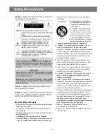
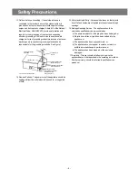
Page 3: ...ould be used only with a cart or stand that is recommended by th manufacturer 3 An appliance and cart combination should be moved with care Quick stops excessive force and uneven surfaces may cause th...

Page 4: ...that objects do not fall and liquids are not spilled into the enclosure through openings 16 Damage Requiring Service The appliance should be serviced by qualified service personnel when a The power su...

Page 5: ...25Hz MTT 111N RV601 Line Out L R Channel Confirm Wow Flut ter is within 0 35 FIG 1 3 000 3 010Hz MTT 111N RV601 Line Out L R Channel Confirm Tape Speed of end position after adjustment at tape start p...

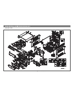
Page 6: ...Exploded View and Mechanical Parts List Model No XL 125 R 5 AXL 122L 124L 125R 123DP 125DP 128L...

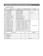
Page 7: ...EQ L 9CD10034L0 ACRYL 1 16 DECO EQ R 9CD10034R0 ACRYL 1 17 KNOB FUNCTION 9CD1342400 ACRYL 4 18 PLATE FUNCTION 9CD0911900 PC 4 19 KNOB POWER 9CD1342600 ABS 1 20 KNOB DISC 9CD1342500 ABS 1 21 A CASSETT...

Page 8: ...FZN 13 S2 SCREW TAPTTITE 7173301011 TT2 BIN 3 0X10 MFZN 18 S3 SCREW TAPTTITE 7173301212 TT2 BIN 3 0X12 BK 18 S4 SCREW TAPTTITE 7173301612 TT2 BIN 3 0X16 BK 2 S5 SCREW TAPTTITE 7173300611 TT2 BIN 3 0X6...

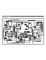
Page 9: ...WIRING DIAGRAM 8 Model No XL 128 R...

Page 10: ...BLOCK DIAGRAM 9 Model No XL 128 R QUAL R DATA R CLK ANALOG VDD1 VSS1 V REF 2 5 6 3 4 1 9 7 8 11 10 VT VCC 16 19 18 15 17 20 22 21 25 23 24 14 13 12 AM OSC VSS2 VSS3...

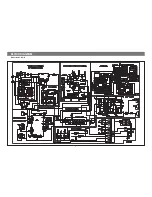
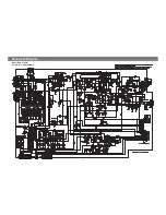
Page 11: ...Schemetic Diagram 10 Model No XL 128 R Ass y Name POWER AMP...

Page 12: ...Schemetic Diagram 11 Model No XL 128 R Ass y Name CD...

Page 13: ...Schemetic Diagram 12 Model No XL 128 R Ass y Name CONTROL...

Page 14: ...Schemetic Diagram 13 Model No XL 128 R Ass y Name TAPE...

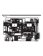
Page 15: ...Schemetic Diagram 14 Model No XL 128 R Ass y Name POWER...

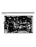
Page 16: ...P C B Pattern Layout 15 Model No XL 128 R Ass y Name MAIN PCB...

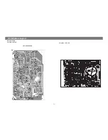
Page 17: ...Model NoXL 128 R Ass y Name CD P C B P C B Pattern Layout 16 Ass y Name TAPE P C B...

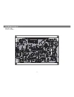
Page 18: ...P C B Pattern Layout 17 Model No XL 128 R Ass y Name CONTROL...

Page 19: ...P C B Pattern Layout Model No XL 128 R Ass y Name POWER PCB 18...

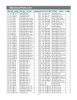
Page 20: ...PER W581GY1005 AWG22 1 0 65 SN 10 AUTO 31 CE517 C ELECTRO CEXF1H479V 50V RSS 4 7MF 5X11 TP 94 JW539 WIRE JUMPER W581GY6095 AWG22 1 0 65 SN 6 AUTO 32 CE518 C ELECTRO CEXF1E470V 25V RSS 47MF 5X11 TP 95...

Page 21: ...E JUMPER W581GY6095 AWG22 1 0 65 SN 6 AUTO 159 R549 550 R CARBON FILM RD AZ273J 1 6 27K OHM J 48 JW309 310 WIRE JUMPER W581GY7595 AWG22 1 0 65 SN 7 5 AUTO 160 R551 R CARBON FILM RD AZ184J 1 6 180K OHM...

Page 22: ...22 1 0 65 SN 6 AUTO 170 R729 R CARBON FILM RD AZ222J 1 6 2 2K OHM J 108 JW795 WIRE JUMPER W581GY12J5 AWG22 1 0 65 SN 12 5 AUTO 171 R730 R CARBON FILM RD AZ101J 1 6 100 OHM J 109 JW796 WIRE JUMPER W581...

Page 23: ...1K 25V B 270PF K AXIAL 79 CE901 904 C ELECTRO CEXF1E470V 25V RSS 47MF 5X11 TP 17 CC209 C CERA CCXF1H103Z 50V F 0 01MF Z TAPPING 80 CE905 C ELECTRO CEXF1E102V 25V RSS 1000MF 13X20 BK 18 CC212 C CERA CC...

Page 24: ...JUMPER W581GY7595 AWG22 1 0 65 SN 7 5 AUTO 207 JW819 WIRE JUMPER W581GY1505 AWG22 1 0 65 GY 15 AUTO 145 JW202 WIRE JUMPER W581GY1005 AWG22 1 0 65 SN 10 AUTO 208 JW820 822 WIRE JUMPER W581GY7595 AWG22...

Page 25: ...R CARBON FILM RD AZ472J 1 6 4 7K OHM J 269 Q908 909 TR TZTC3198Y KTC3198Y 1815Y AUTO 332 R442 443 R CARBON FILM RD AZ222J 1 6 2 2K OHM J 270 R002 WIRE JUMPER W581GY6095 AWG22 1 0 65 SN 6 AUTO 333 R44...

Page 26: ...0HA UPC1330HA 10 D916 DIODE DZN4148 1N4148 AUTO 52MM 41 IC603 IC 1BU4094BCF BU4094BCF SOP16 11 DB901 902 DIODE DKBJ604G KBJ604G 42 JW601 603 WIRE JUMPER W581GY7595 AWG22 1 0 65 SN 7 5 AUTO 12 F901 FUS...

Page 27: ...LM RD AZ562J 1 6 5 6K OHM J 101 R619 620 R CARBON FILM RD AZ123J 1 6 12K OHM J 102 R621 622 R CARBON FILM RD AZ153J 1 6 15K OHM J 103 R625 626 R CARBON FILM RD AZ102J 1 6 1K OHM J 104 R627 628 R CARBO...

Reviews: