Power Train
Testing And Adjusting
Armature Terminal Test
Test for Continuity
Brush Test
1.
Put the digital multimeter Function/Range Switch
on the 200 ohm resistance (½) scale.
2.
Put one test lead to an outer armature terminal
and the other test lead to each brush lead that
connects to that terminal. There must be less than
one ohm resistance.
3.
Do Step 2 again with the other outer armature
terminal and brush leads.
4.
Too much resistance is an indication of corrosion
at the connection to the terminal.
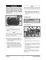
Ground Test
Ground Test
(1) Armature Terminal. (2) Motor Housing.
1.
Put the digital multimeter Function/Range Switch
on the 20M resistance (½) scale.
2.
Put one test lead to an outer brush terminal (1)
and the other test lead to the motor housing (2).
There must be more than one megohm resistance.
3.
Do the test again with one test lead on the other
outer brush terminal.
Brush Holder Test
Brush Holder Test
(1) Brush Holder. (2) End Bell.
1.
The brush holders are mounted on the rocker at
the commutator end of the motor. Make a visual
inspection of the brush holders and the rocker.
2.
Put digital multimeter Function/Range Switch on
the 200 ohm resistance (½) scale. Put one test
lead to a brush holder (1) and the other test lead
to the end bell (2). The meter must show overload
(OL).
3.
Check each brush holder. If meter reading is low,
the brush holder is grounded. Replace the rocker.
Tools Needed
Digital Multimeter Or Equivalent
1
Tools Needed
Digital Multimeter Or Equivalent
1
19
2
1
2
1


