


Service manual SC-150
-60-
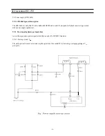
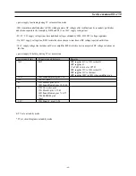
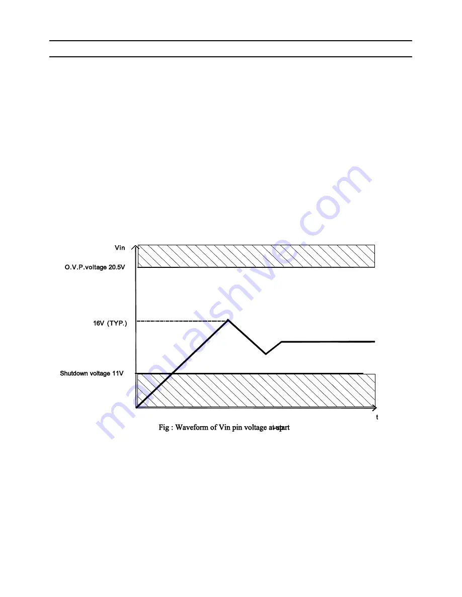
When the power switch is pushed on, V
IN
increases slowly. During this time, C806 is charged through R802.
As soon as V
IN
reaches 16V, the STR-F6654 control circuit starts operating. Then, V
IN
is obtained by smoothing the
winding voltage which appears between pin6 and pin7 of the SMPS transformer.
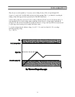
As this winding voltage does not increase to the set voltage immediately after the control circuit starts operating, V
IN
starts dropping. However, as this winding voltage reaches the set value before V
IN
voltage drops to the shutdown
voltage (at 11V), the control circuit continues operating (see below V
IN
voltage at start-up). R805 resistor prevents that
V
IN
pin voltage varies according to the secondary side output current.
V
IN
must be set higher than the shutdown voltage (V
IN
(off) = 11V
max
) and lower than the O.V.P. (overvoltage
protection) operating voltage
(V
OVP
= 20.5V
min
)
Summary of Contents for CHASSIS : SC-150 Model : DSC-3220E
Page 35: ...Service manual SC 150 34 Block diagram TDA6107Q...
Page 44: ...Service manual SC 150 43 5 Circuit description 5 1 Block diagram...
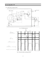
Page 62: ...Service manual SC 150 61 5 9 2 2 STR F6654 oscillating operation...
Page 82: ...Service manual SC 150 81 8 1 PCB MAIN...
Page 83: ...Service manual SC 150 82 8 2 PCB UNION...
Page 84: ...Service manual SC 150 83 9 1 Schematic Diagram MAIN...
Page 85: ...Service manual SC 150 84 9 2 Schematic Diagram UNION...
Page 86: ......


