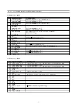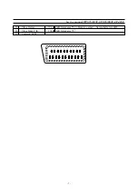
Entering Factory mode Option bits
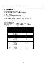
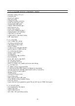
To switch the TV set into FACTORY mode, use the factory remote control, and press on “SVC”. The factory menu
will appear on the screen, showing “FACTORY Vx.xxX” (where x.xx is the software version) and X is the project. A is
the correct project for WP895/895F, CP-485/885F, and B is for the CP885 chassis.
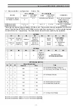
To find the option bits, push the button “OPT” once. Then “00000000 OPTION” will appear (assuming that all bits are
already zero) to indicate all 8 option bits. To find OPTION2 press the button “OPT” a second time. From left to right,
bits 7 to 0 are shown.
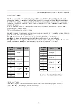
Toggling option bits
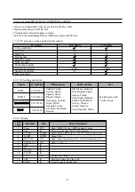
This is done from the user remote control, as there are no unallocated keys available from the factory remote control.
Each bit, from bit 7 to bit 0 is represented by its own key. Each key will, with repeated use, toggle on/off the
associated bit. See the table below for the keys to use.
After setting option bits
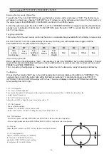
Before pushing on the shipping key, “AGC”, it is necessary to push the “NORMAL” key to obtain NORMAL I. This will
reset all the sound and brightness settings to a factory defined level, as well as some other settings such as sound
PRESET and WAKE TIME/PROG.
Then, on pushing the shipping key, these levels are memo rised in the television, ready for packing and delivery.
Verification
On pushing the shipping “AGC” key, a four digit hexadecimal number is displayed in addition to “SHIPPING”. This
number is there to verify the option bits setting that has been entered. For example the binary code 0000 0111
(OPTION2) 1100 0010 (OPTION) will give 07 C2 hex. The order of display is therefore OPTION2 then OPTION
when reading from left to right
.
Bit
B7
B6
B5
B4
B3
B2
B1
B0
User
remote
control key
Text
HOLD
Text
SubPage
Mode
Text
Reveal
Text
Double
Height
Red
Green
Yellow
Blue
- 16-
3-4 TV set Alignment
3-4-1- Local oscillator alignment
Tune a colour bar pattern. The frequency of the signal carrier must be accurate ( Max +/- 10Khz deviation from the
nominal channel frequency).
Find “AFT” item in service mode.
Adjust the coil L150 to bring the cursor to central position : 32.
3-4-2- G2 alignment
- Tune a colour bar pattern.
- Find the “G2 - SCREEN” item in service mode.
- Adjust screen volume ( on FBT ) to bring the cursor to central position : 32.
3-4-3- White balance
- Select a dark picture and adjust RED BIAS and GRN BIAS to the desired colour temperature.
- Select a bright picture and adjust RED, GRN and BLUE GAIN to the desired colour temperature.
3-4-4- Focus
Adjust the Focus volume ( on FBT ) to have the best resolution on screen.
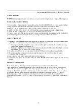
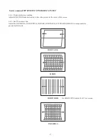
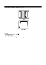
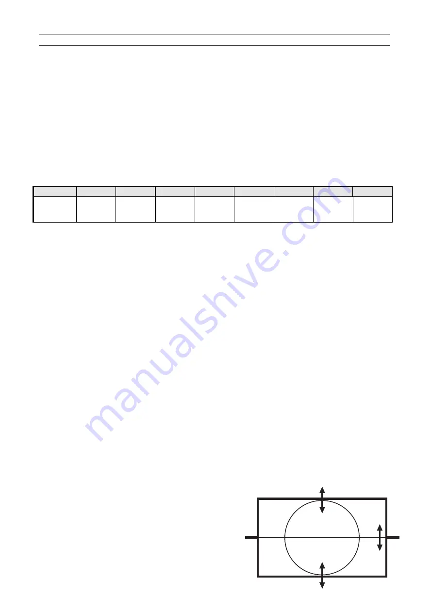
3-4-5- Vertical geometry
Adjust V.LINEAR (linearity), S CORRECT
(S. Correction), VERT SIZE (Vertical
amplitude), VERT CENT (vertical centring)
to compensate for vertical distortion.
Service manual WP 895/895F, CP885/885F, CP485F
Summary of Contents for CP-485F
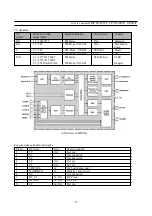
Page 33: ... 32 Service manual WP 895 895F CP885 885F CP485F Block diagram TDA8944J ...
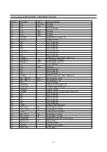
Page 36: ... 35 Service manual WP 895 895F CP885 885F CP485F ...
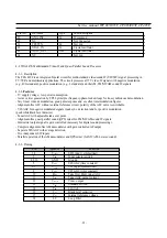
Page 38: ... 37 Service manual WP 895 895F CP885 885F CP485F Block diagram TDA6107Q ...
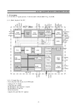
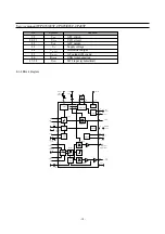
Page 43: ... 42 Service manual WP 895 895F CP885 885F CP485F 5 Circuit description 5 1 Block diagram ...
Page 61: ... 60 Service manual WP 895 895F CP885 885F CP485F 5 9 2 2 STR F6654 oscillating operation ...
Page 67: ... 66 Service manual WP 895 895F CP885 885F CP485F ...
Page 87: ...Service Manual WP 895 895F CP885 885F CP485F 86 7 Exploded View 7 1 DWX 28W5 ...
Page 88: ...Service Manual WP 895 895F CP885 885F CP485F 87 7 Exploded View 7 2 DWF 28W8 ...
Page 89: ...Service Manual WP 895 895F CP885 885F CP485F 88 7 Exploded View 7 3 DTF 29U8 ...
Page 90: ...Service Manual WP 895 895F CP885 885F CP485F 89 7 Exploded View 7 4 DTP 28A7 ...
Page 91: ...Service Man ual WP 895 895F CP885 885F CP485F 90 7 Exploded View 7 5 DTP 28B1 ...
Page 92: ...Service Man ual WP 895 895F CP885 885F CP485F 91 7 Exploded View 7 6 DTP 28G7 ...
Page 93: ...Service Manual WP 895 895F CP885 885F CP485F 92 7 Exploded View 7 7 DTP 28G8 ...
Page 94: ...Service Manual WP 895 895F CP885 885F CP485F 7 8 DWF 28W9 93 7 Exploded View ...
Page 95: ... 94 Service Manual WP 895 895F CP885 885F CP 485F 7 9 DTB 21U7 7 Exploded view ...
Page 96: ...SCHEMATIC DIAGRAM WP 895 CP 885 ...
Page 97: ...SCHEMATIC DIAGRAM WP 895F CP 885F ...
Page 98: ...SCHEMATIC DIAGRAM CP 485F ...
Page 99: ......
Page 100: ......
Page 101: ... CP 485F ...

