- 50 -
Service manual WP 895/895F, CP885/885F, CP485F
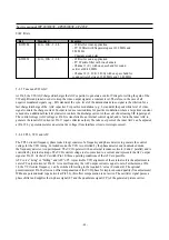
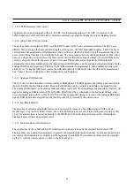
5-3-20 EHT Compensation
The vertical waveform can be scaled according to the average beam current. This is used to compensate the effects of
electric high-tension changes due to beam current variations. EHT compensation for East/West deflection is done with
an offset corresponding to the average beam current.
5-3-21 Reset Function
Reset of all VDP functions is performed by the RESQ pin. When this pin becomes active, all internal registers and
counters are lost.
5-3-22 Standby and Power-On
The VDP does not have a standby mode. To disable all the analogue and digital video functions, it is necessary to
switch off the supplies for analogue front-end (VSUP AF ), analogue back-end (VSUP AB ) and digital circuitry
(VSUP D ).
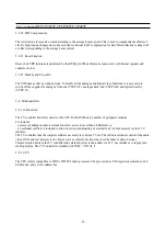
5-4- Microcontroller
5-4-1 Introduction
The TV controller basically consists of the CPU, RAM, ROM, and a number of peripheral modules.
For instance:
– a memory banking module is included to allow access to more than 64 kB memory.
– a bootloader software is included to allow in-system-downloading of external code to Flash memory via the I 2 C
interface.
The TV controller runs the complete software necessary to control a TV set. The software includes control of the audio,
video, OSD, and text processors on chip, as well, as control of external devices like tuner or stereo decoder.
Communication between the TV controller and external devices is done either via I 2 C bus interface or via program-
mable port pins. The TV Controller is clocked with f OSC = f XTAL /2.
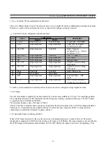
5-4-2 CPU
The CPU is fully compatible to WDC’s W65C02 micro-processor. The processor has 8-bit registers/accumulator, an 8-
bit data bus, and a 16-bit address bus.
Summary of Contents for CP-485F
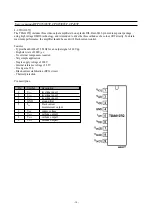
Page 33: ... 32 Service manual WP 895 895F CP885 885F CP485F Block diagram TDA8944J ...
Page 36: ... 35 Service manual WP 895 895F CP885 885F CP485F ...
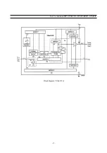
Page 38: ... 37 Service manual WP 895 895F CP885 885F CP485F Block diagram TDA6107Q ...
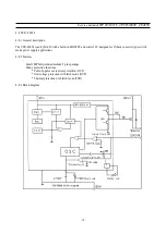
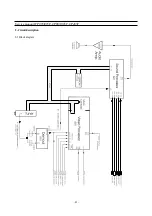
Page 43: ... 42 Service manual WP 895 895F CP885 885F CP485F 5 Circuit description 5 1 Block diagram ...
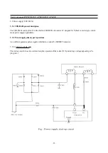
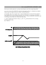
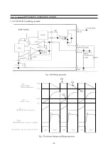
Page 61: ... 60 Service manual WP 895 895F CP885 885F CP485F 5 9 2 2 STR F6654 oscillating operation ...
Page 67: ... 66 Service manual WP 895 895F CP885 885F CP485F ...
Page 87: ...Service Manual WP 895 895F CP885 885F CP485F 86 7 Exploded View 7 1 DWX 28W5 ...
Page 88: ...Service Manual WP 895 895F CP885 885F CP485F 87 7 Exploded View 7 2 DWF 28W8 ...
Page 89: ...Service Manual WP 895 895F CP885 885F CP485F 88 7 Exploded View 7 3 DTF 29U8 ...
Page 90: ...Service Manual WP 895 895F CP885 885F CP485F 89 7 Exploded View 7 4 DTP 28A7 ...
Page 91: ...Service Man ual WP 895 895F CP885 885F CP485F 90 7 Exploded View 7 5 DTP 28B1 ...
Page 92: ...Service Man ual WP 895 895F CP885 885F CP485F 91 7 Exploded View 7 6 DTP 28G7 ...
Page 93: ...Service Manual WP 895 895F CP885 885F CP485F 92 7 Exploded View 7 7 DTP 28G8 ...
Page 94: ...Service Manual WP 895 895F CP885 885F CP485F 7 8 DWF 28W9 93 7 Exploded View ...
Page 95: ... 94 Service Manual WP 895 895F CP885 885F CP 485F 7 9 DTB 21U7 7 Exploded view ...
Page 96: ...SCHEMATIC DIAGRAM WP 895 CP 885 ...
Page 97: ...SCHEMATIC DIAGRAM WP 895F CP 885F ...
Page 98: ...SCHEMATIC DIAGRAM CP 485F ...
Page 99: ......
Page 100: ......
Page 101: ... CP 485F ...

