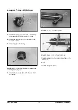
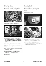
Daewoo D35S-2, Disassembly/Assembly
The Daewoo D35S-2 user manual is available for download, completely free on 88.208.23.73:8080. This comprehensive manual provides step-by-step instructions for disassembly and assembly, offering users a handy resource to maintain and troubleshoot their Daewoo D35S-2 product efficiently. Access the manual now and enhance your product experience.
Share
Download


Reviews:
No comments
Related manuals for D35S-2
R55
Brand: RANKO Pages: 67

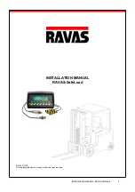
1100
Brand: Ravas Pages: 14
XC Series
Brand: HANGCHA Pages: 95
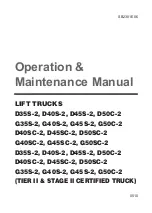
D35S-2
Brand: Daewoo Pages: 172
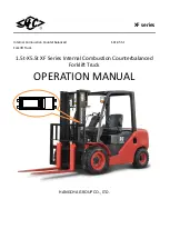
XF Series
Brand: HANGCHA Pages: 73
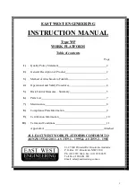
WP
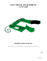
Brand: East West Engineering Pages: 11

Bendi B40i4
Brand: Landoll Pages: 142
LiftPlus
Brand: Magliner Pages: 40
6145
Brand: VALLEY CRAFT Pages: 8

782008-R3
Brand: cascade corporation Pages: 12

H170FT
Brand: Hyster Pages: 21
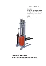
SPM1516
Brand: Noblelift Pages: 8

PDH
Brand: Big Joe Pages: 28
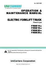
FRSB14-8
Brand: UniCarriers Pages: 136

EPS14Pi
Brand: BYD Pages: 39

FD160-2
Brand: UniCarriers Pages: 158

ESC 316
Brand: Jungheinrich Pages: 157
SafeLoad
Brand: Ravas Pages: 40


