-9-
ALIGNMENT INSTRUCTIONS
1) SCREEN ADJUSTMENT(S2)
-. Enter the service mode and select service adjustment S2.
-. You can see the one horizontal line on the screen.
-. Adjust the Screen Control Volume(located on FBT)
so that the horizontal line onscreen may be disappeared.
-. Press S2 button again to make the screen normal condition.
< CAUTION >
IN THE SCREEN ADJUSTMENT MODE,
DON’T PRESS OTHER BUTTONS EXCEPT S2 BUTTON.
2) FOCUS ADJUSTMENT
-. Turn in a local station and adjust the Focus Control knob (located on FBT)
for best picture details at high light condition.
3) RF AGC ADJUSTMENT(S5)
-. Enter the service mode and select service adjustment S5.
-. Receive the RF 100% full color bar 60dBuV attenuation signal.
-. Start RF AGC Adj.Start using Service Remocon S5.
-. Check for RF AGC Adj. OK OSD.
-. Press the DISPLAY button to memorize the data.
4) GEOMETRIC ADJUSTMENTS(S6)
-. Enter the service mode and select service adjustment S6.
4-1). Horizontal Position Adjustment
Select H-CENTER item, adjust H-CENTER data value to obtain proper
horizontal centering of the internal cross pattern at the left and right of
the screen.
4-2). Vertical Position Adjustment
Select V-CENTER item, adjust V-CENTER data value to center the raster
properly on the screen.
4-3). Vertical Size Adjustment
“Select “”V.SIZE”” item, adjust “”V.SIZE”” data value to proper vertical size. “
-. Press the DISPLAY button to memorize the data.
5) WHITE BALANCE ADJUSTMENT(S8)
-. Receive a good local channel.
-. Enter the service mode and select service adjustment S8.
-. Using button, adjust service adjustment data of RD/GD/BD and
RB/GB/BB until a good gray scale with normal whites is obtained.
-. Press the DISPLAY button to memorize the data.
6) DIGITAL PRESET(D.P) ADJUSTMENTS(S9)
-. Receive a good local channel.
-. Enter the service mode and select service adjustment S9.
-. Select SUB BRIGHT item,
adjust SUB BRIGHT data value to obtain normal brightness level.
-. Press the DISPLAY button to memorize the data.
7) FACTORY OUTGOING MODE(S12)
-. If you select the S12, then the set becomes factory outgoing status.
“ -. You can see the OSD “”outgoing OK””.”
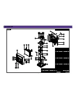
4-3. ASSEMBLY ADJUSTMENTS
Summary of Contents for DDQ-20L6SC
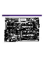
Page 11: ...5 SCHEMATIC DIAGRAM 10 5 1 MAIN CIRCUIT DIAGRAM ...
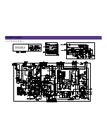
Page 12: ...SCHEMATIC DIAGRAM 11 5 2 POWER CIRCUIT DIAGRAM ...
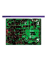
Page 22: ...7 PRINTED CIRCUIT BOARD 21 7 1 PCB MAIN ...
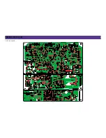
Page 23: ...PRINTED CIRCUIT BOARD 22 7 2 PCB POWER ...
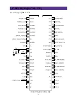
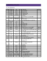
Page 24: ... 23 9 IC DESCRIPTION U COM I701 9 1 U COM I701 PIN ASSIGN ...
Page 27: ... 26 10 CHIP COMPONENTS POSITION PCB MAIN ...
Page 41: ......

