2.1.7. Valve clearance
1) Turn the crank shaft so that the piston in No. 1 cylinder reaches the TDC on compression
stroke, then adjust the valve clearance.
2) After releasing the lock nut for the rocker arm adjusting screw, insert a feeler gauge of speci-
fied thickness into the clearance between the rocker arm and valve stem, and adjust the
clearance with the adjusting screw. Fully tighten the lock nut when a correct adjustment is
obtained.
3) Carry out the same adjusting operation according to the firing order(1-5-3-6-2-4)
(Valve clearance(with engine cooled): 0.30mm for both intake and exhaust)
2.1.8. Cylinder compression pressure
1) Stop the engine after warming up, then remove the nozzle holder assembly.
2) Install a special tool(gauge adapter) in nozzle holder hole and mount the compression gauge
in position of the nozzle holder.
3) Cut off fuel circulation, rotate the starter, then measure compression pressure in each cylin-
der.
6
Testing conditions: Coolant temperature 20
C
, Engine speed, 200 rpm (10 turns)
2.1.9. Injection nozzle
1) Assemble a nozzle to a nozzle tester.
2) Check injection pressure, and adjust the nozzle using the adjusting shim if the pressure does
not meet the specified limit.
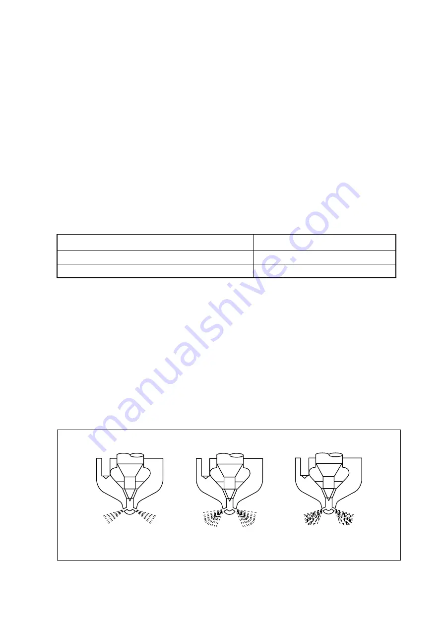
3) Check nozzle spray patterns and replace if damaged.
Standard
28 kg/cm
2
over
Limit
24 kg/cm
2
or less
Difference between each cylinder
L
10% or less
- 24 -
Normal
Abnormal
Abnormal
<Figure 2-1> Nozzle spray patterns
EFM1006I


