-40-
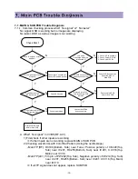
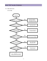
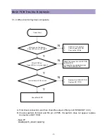
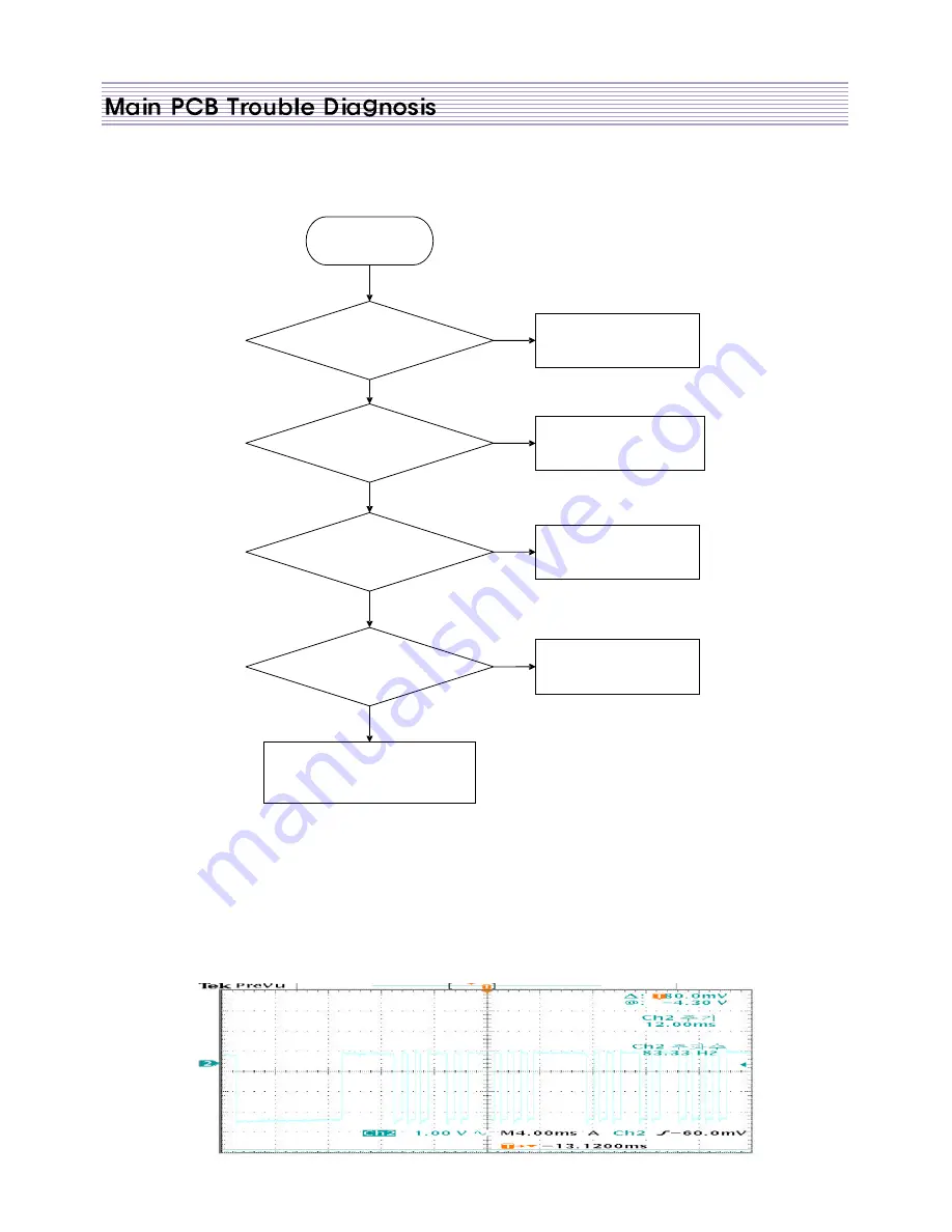
7-1-4. When Remote Controller does not operate.
Check S tart
After t urn on t he powe r,
does LED t urn o n red light?
Is Remote Co ntroller working?
Does set wo rking b y p ressing
a KEY butto n?
1.
IR receiving B LOCK of MAIN PCB is
not wo rking.
2. Re place MAIN PCB
Check the connection between
LED PCB and MAIN PCB.
Chec k the Battery o f Remote
Controller
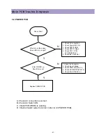
1.
Check AC co nnect ion
2.
Check Powe r S/ W ON
3.
Chec k o ther BLOCks
When you press button, do es wavefor m
from fir st p in of P W7 nor mal?
Replace LED PCB
Y
Y
Y
Y
N
N
N
N
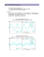
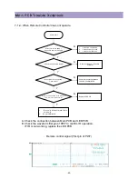
A. Check the connection between Main PCB and LED PCB.
B. Check the waveform first pin of PW7 to confirm IR operation.
IF IR is not working, replace the LED PCB
Remote control signal (First pin of PW7)
Summary of Contents for DLP-2612
Page 7: ...7 3 2 POWER BLOCK DIAGRAM...
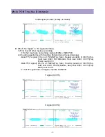
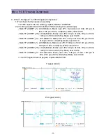
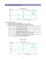
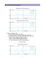
Page 34: ...34 G Signal LCA4 B Signal LCA5 Clock RCA10 near ICA10...
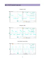
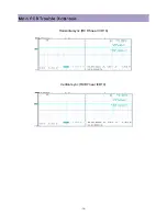
Page 36: ...36 Horizontal sync RCD6 near ICD10 Vertical sync RCD7 near ICD10...
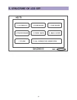
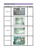
Page 45: ...45 COMPONENT PICTURE REMARK 1 LCD MODULE 2 MAIN BOARD 3 SUB BOARD 4 POWER BOARD...
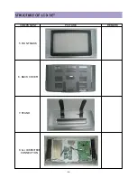
Page 46: ...46 COMPONENT PICTURE REMARK 5 RONT MASK 6 BACK COVER 7 STAND 8 ALL CONNECTROR CONNECTION...
Page 60: ...11 SCHEMATIC DIAGRAM 62...
Page 61: ...SCHEMATIC DIAGRAM 63...
Page 62: ...SCHEMATIC DIAGRAM 64...
Page 63: ...SCHEMATIC DIAGRAM 65...
Page 64: ...SCHEMATIC DIAGRAM 66...
Page 65: ...SCHEMATIC DIAGRAM 67...
Page 66: ...SCHEMATIC DIAGRAM 68...
Page 67: ...SCHEMATIC DIAGRAM 69...
Page 68: ...SCHEMATIC DIAGRAM 70...
Page 69: ...SCHEMATIC DIAGRAM 71...
Page 70: ...SCHEMATIC DIAGRAM 72...
Page 71: ...SCHEMATIC DIAGRAM 73...
Page 72: ...SCHEMATIC DIAGRAM 74...
Page 73: ...SCHEMATIC DIAGRAM 75...
Page 74: ...SCHEMATIC DIAGRAM 76...
Page 75: ...77 10 1 DLP 3212APSB...
Page 76: ...78 10 2 DLP 2612APSB...

