- 25 -
correctly plugged to the fixed positions, or re-plug them.
B.
Check the resistors or capacitors of U8 on the main board, or those adjacent to
IC to see if there is any hollow soldering, cold soldering, wrong part, or
misplaced soldering.
C.
If the above actions are not working, replace the loader. If it is still not working,
replace the main board.
z
T21
、
no video / abnormal
9
Main Board
A.
Remove the top cover, check all flat cables in the system to see if they are
correctly plugged to the fixed positions, or re-plug them.
B.
Check the resistors or resistor-array adjacent to U1 Pin18~21 on the main board
or IC to see if there is any short circuit, hollow soldering or cold soldering. Rule
out the problem if there is any.
C.
Use oscilloscope to measure if YM1 generates 27MHz. If it does not generate
said frequency, and the problems such as cold or hollow soldering have been
ruled out, it could be YM1 NG. Replace YM1.
D.
Check U1 to see if it has bad contact or if U6 (F/W) IC has any problem.
E.
If the above actions are not working, replace the Main Board.
9
DVD ROM (less likely to happen)
A.
If it is useless to change the main board, then replace the loader.
z
T22
、
Video no video / abnormal
9
Main Board
A.
Remove the cover. Check J9 on the main board to see if there is any cold or
hollow soldering and rule out the problem.
B.
Remove the top cover, check all flat cables in the system to see if they are
correctly plugged to the fixed positions, or re-plug them.
C.
Check RLC following CVBS to see if there is any wrong parts, cold and hollow
soldering, short circuit, broken circuit, broken parts and rule out the problem.
D.
If the above actions do not work, then check U1Pin211 and Pin214-215 to see if
there is any cold or hollow soldering and short circuit problem and rule out the
problem.
E.
If the above actions are not working, replace the Main Board.
z
T23
、
VCD abnormal picture
9
Main Board
A.
Check U1 and U6 to see if there is any cold or hollow soldering and short
circuit problem and rule out the problem.
B.
Check the resistors or capacitors of J2, U1 or those adjacent to IC to see if there
is any hollow soldering, cold soldering, wrong part, or misplaced soldering.
C.
If the above actions are not working, replace the Main Board.
Summary of Contents for DPC-7600
Page 7: ... 5 2 3 System Block Diagram ...
Page 10: ... 8 4 Physical Characteristics ...
Page 11: ... 9 ...
Page 12: ... 10 4 1 Outline Dimension z 210mm L x 155mm W x 43 68mm H ...
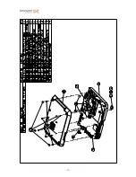
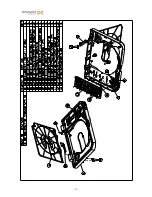
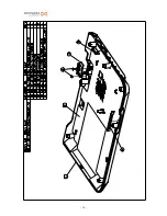
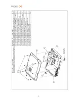
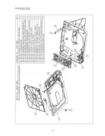
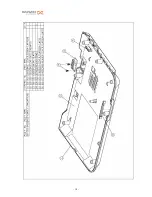
Page 13: ... 11 4 2 Spare Parts Structure Drawing DPC 7600 ...
Page 14: ... 12 ...
Page 15: ... 13 ...
Page 16: ... 14 ...
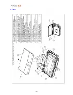
Page 17: ... 15 DPC 8600 ...
Page 18: ... 16 ...
Page 19: ... 17 ...
Page 20: ... 18 ...
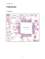
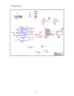
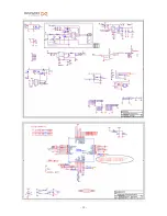
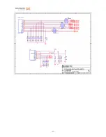
Page 34: ... 32 7 Schematic 7 1 Main Board ...
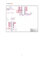
Page 35: ... 33 ...
Page 36: ... 34 ...
Page 37: ... 35 ...
Page 38: ... 36 ...
Page 39: ... 37 ...
Page 40: ... 38 ...
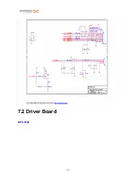
Page 41: ... 39 7 2 Driver Board DPC 7600 ...
Page 46: ... 44 7 3 Battery Board ...


