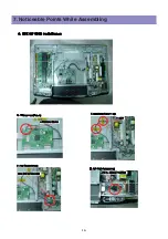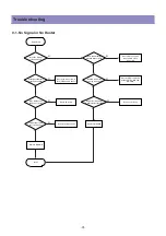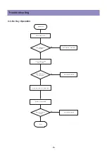
-30-
Trouble shooting
- Caution 1 !!
When disconnecting / connecting connectors, you MUST disconnect the AC Power.
And check the direction and position of the connectors before working.
- Caution 2 !!
Whenever you reassemble connectors connecting High Voltage Board and POWER PCB,
remaining voltage still exists in the POWER PCB could cause electric shock and damage
the set.
Therefore always reassemble the connectors several minutes after AC power disconnect.
To be more careful, using a Multimeter you should check to see if Vs is less than 10V
and then connect connectors.
Definition
- Red LED - Stand by state (ready for operating)
- Green LED - The set is turned on and operating
- Shut Down - While green LED, power PCB does not make any operating sound or noise
(i.e. Power relay does not operate normally)
- Weak Discharge - The screen looks like BLACK, but there are little discharged cells on the
screen
- Abnormal Discharge - Shows unexpected discharged cells on the image
- No Signal - OSD is working but no images are displaying
- No Raster - Not even OSD is displaying
Summary of Contents for DPX-32F1BMB
Page 2: ......
Page 8: ...8 The Feature of Inside 3 3 Power Specification...
Page 16: ...7 Noticeable Points While Assembling 16...
Page 17: ...Noticeable Points While Assembling 17...
Page 21: ...21 5 Importing HEX file for upgrade Software Upgrade Methord...
Page 37: ...37 Trouble shooting 9 6 No Key and Remote Control Operation...
Page 41: ......
Page 42: ...42 11 Exploded View...


