30
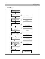
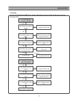
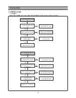
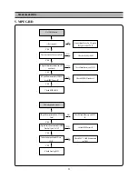
TROUBLESHOOTING
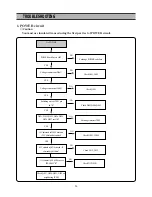
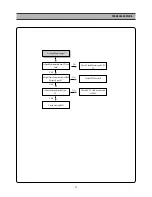
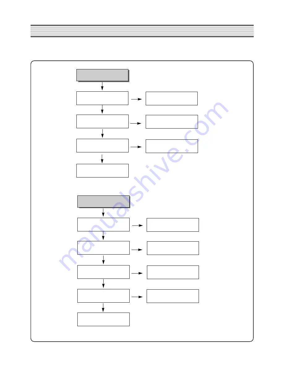
No VIDEO output from JK301 yellow
pin
TV setting on SETUP MENU is PAL
mode?
YES
NO
NO
NO
YES
YES
Is there Video signal from P205 pin #20?
Is there Video signal from
Q100,Q101 emitter ?
Check D100,101,102,103
Change setting to PAL mode
Check FFC CABLE connected to P205
and MPEG Decoder IC pin #100-#106
Check Q100, Q101
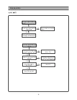
4. VIDEO circuit
✓
Caution
Before the VIDEO circuit test, check SETUP MENU setting first by remote controller.
No Component Video output from
JK101
TV setting on SETUP MENU is PAL mode?
YES
NO
NO
NO
YES
YES
VIDEO output of SETUP MENU is
set on Component?
Is there Video signal from P205 pin
#17,18,19?
Check D116,117,118,119,120,121
Change setting to PAL mode
Change setting to Component
Check FFC CABLE connected to P205
and MPEG Decoder IC pin #100-#106
NO
YES
Is there Video signal from
Q104,Q105,Q106 emitter ?
Check Q104,Q105,Q106
Summary of Contents for DQD-2100D
Page 5: ...4 CIRCUIT DIAGRAM POWER SUPPLY SCHEMATIC DIAGRAM DQD 6100 220V ...
Page 6: ...5 CIRCUIT DIAGRAM VIDEO ...
Page 7: ...6 CIRCUIT DIAGRAM AUDIO ...
Page 8: ...7 CIRCUIT DIAGRAM VFD JOG ...
Page 9: ...8 CIRCUIT DIAGRAM ETC ...
Page 10: ...9 CIRCUIT DIAGRAM VCR_INT DVD ...
Page 11: ...10 CIRCUIT DIAGRAM ATAPI DVD ...
Page 12: ...11 CIRCUIT DIAGRAM CPU ZR36703 DVD ...
Page 13: ...12 CIRCUIT DIAGRAM MPEG DECODER ...
Page 46: ...45 COMPONENTS LOCATION GUIDE ON PCB BOTTOM VIEW ...
Page 47: ...46 JOG COMPONENTS LOCATION GUIDE ON PCB BOTTOM VIEW M P E G ...
Page 48: ...47 DISASSEMBLY ...
Page 49: ...48 DISASSEMBLY ...
Page 50: ...49 DISASSEMBLY ...
Page 51: ...50 DISASSEMBLY ...

