2
1. Safety Instruction
1. When all services are carried out, every item required in this manual needs to be followed
and the services should be performed by A/S man.
2. The following general items should be performed before staring the services.
1) Unplug the power.
2) Uncover the cabinet.
3) To prevent a danger of shock, touch a terminal of plug on the chassis ground and discharge
a remaining voltage.
4) Check if all parts are in the proper places, omitted or burned.
5) Check the soldering state of all parts, if a clad copper is loose or peeled off and if there is a
short between clad coppers.
6) When all the articles mentioned above are normal, plug the power and refer to “Fault
diagnosis according to cause and symptom” of this manual for service according to screen
state.
3. Pay attention to a basic wiring and check a damaged part if a disconnected circuit is found
and replace it with a new one.
4. The equal rated parts should be used depending on the parts list of this manual when a part
needs to be replaced. Because some electronic parts and appliances have safety-related
features, an electric shock, file or X-RAY radiation can be caused if no equal rated parts are
used.
5. When a part needs to be replaced and soldered on PCB, the part should be inserted in the
right position and not contact with even a terminal of other part. Especially, a high voltage
resistance should be inserted with 10mm away from the PCB.
6. Since approx. 30KV high voltage is applied to the Braun tube in operating the TV set, a little
X-RAY can be radiated. If the voltage is too high, harmful X-RAY can result in a danger.
Therefore, A/S man with sufficient knowledge about high voltage needs to perform the
service. Especially, be sure to discharge the anode of the Braun tube on the chassis ground
of TV set before starting the repair.
7. Examine the followings before finishing the service.
1) Check if all protecting components have been assembled.
2) Keep the lead line away from high voltage or high temperature parts and check if all wires
have been connected.
3) Check a leakage current to protect a user from a shock.
Observances for safe service
Summary of Contents for DSJ-4720CRU
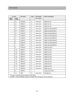
Page 14: ...13 IC Description...
Page 15: ...14 IC Description...
Page 16: ...15 IC Description...
Page 17: ...16 IC Description...
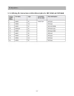
Page 19: ...18 IC Description 5 2 Pin Circuits VSP94X5B VSP94X7B...
Page 20: ...19 IC Description 5 3 Application Circuit 5 3 1 Application Example for QFP80 package...
Page 21: ...20 IC Description 5 4 Pin Description CXA2150AQ...
Page 22: ...21 IC Description...
Page 23: ...22 IC Description...
Page 24: ...23 IC Description...
Page 25: ...24 IC Description...
Page 26: ...25 IC Description...
Page 27: ...26 IC Description...
Page 28: ...27 IC Description...
Page 29: ...28 IC Description...
Page 30: ...29 IC Description...
Page 52: ...51 8 Schematic Diagram 1 Block Diagram...
Page 53: ...52 Schematic Diagram 2 Power...
Page 54: ...53 Schematic Diagram 3 Convergence AMP...
Page 55: ...54 Schematic Diagram 4 Convergence Module...
Page 56: ...55 5 CRT Amp Schematic Diagram...
Page 57: ...56 6 IF Module Schematic Diagram...
Page 58: ...57 7 AV Main Schematic Diagram...
Page 59: ...58 8 Micom Module Schematic Diagram...
Page 60: ...59 9 Control Union Schematic Diagram...
Page 61: ...60 1 Main PCB 9 PRINTED CIRCUIT BOARD...
Page 62: ...61 2 Power PCB PRINTED CIRCUIT BOARD...
Page 63: ...62 3 Convergence Module PCB PRINTED CIRCUIT BOARD...
Page 64: ...63 4 IF Module PCB PRINTED CIRCUIT BOARD...
Page 65: ...64 5 CRT PCB PRINTED CIRCUIT BOARD...
Page 66: ...65 6 UNION PCB PRINTED CIRCUIT BOARD...
Page 67: ...66 1 DSJ 4710CRU 10 EXPLODED VIEW...
Page 68: ...67 2 DSJ 4720CRU EXPLODED VIEW...
Page 69: ......


