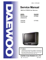
Service manual CP-785A
Contents
1 - Main features ................................................................................................................................. 2
1-1 Specifications .................................................................................................................... 2
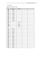
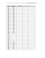
1-2 Channel table .................................................................................................................... 4
2 - Safety instruction .......................................................................................................................... 7
3 - Alignment instructions ................................................................................................................. 8
3-1 Microcontroller configuration : Service mode .................................................................... 8
3-2 Microcontroller configuration : Option................................................................................ 8
3-3 TV set Alignment ............................................................................................................... 8
4 - IC description ................................................................................................................................ 10
4-1 TDA936x TV signal processor - TXT with embedded
m
-Controller. .................................. 10
4-2 MSP3415D Multistandard Sound Processor ..................................................................... 18
4-3 TDA894xJ Stereo Audio Amplifier..................................................................................... 22
4-4 TDA835xJ Vertical Amplifier.............................................................................................. 23
4-4-1 TDA8358J............................................................................................................... 24
4-5 TDA6107Q ........................................................................................................................ 25
4-6 24C08 8 Kbit EEPROM ..................................................................................................... 26
4-7 STR-F6654 ....................................................................................................................... 27
5 - Circuit description......................................................................................................................... 29
5-1 Block diagram.................................................................................................................... 29
5-2 IF ....................................................................................................................................... 33
5-3 Source switching ............................................................................................................... 34
5-4 u-Controller I/O pin configuration and function .................................................................. 34
5-5 Sound processing.............................................................................................................. 35
5-6 Sound amplification ........................................................................................................... 37
5-7 Vertical deflection .............................................................................................................. 37
5-8 Power supply (STR-F6654) ............................................................................................... 39
5-9 TV start-up, TV normal run and stand by mode operations .............................................. 43
6 -Service parts list............................................................................................................................. 50
FS-59T90 & FS-68T90 ........................................................................................................... 50
(DTE-25G5THS & DTE-29G5TH)
7 - Exploded view ............................................................................................................................... 59
8 - PCB Layout ....................................................................................................................................
9 - Circuit Diagram..............................................................................................................................
61
62
Summary of Contents for DTE-25G5THS
Page 15: ...Service manual CP 785A 14...
Page 18: ...Service manual CP 785A 17...
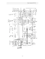
Page 30: ...Service manual CP 785A 29 5 Circuit description 5 1 Block diagram...
Page 60: ......
Page 61: ......
Page 62: ......

