24
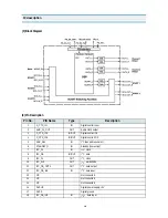
IC description
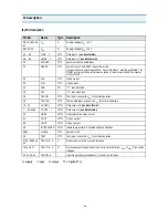
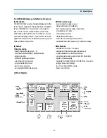
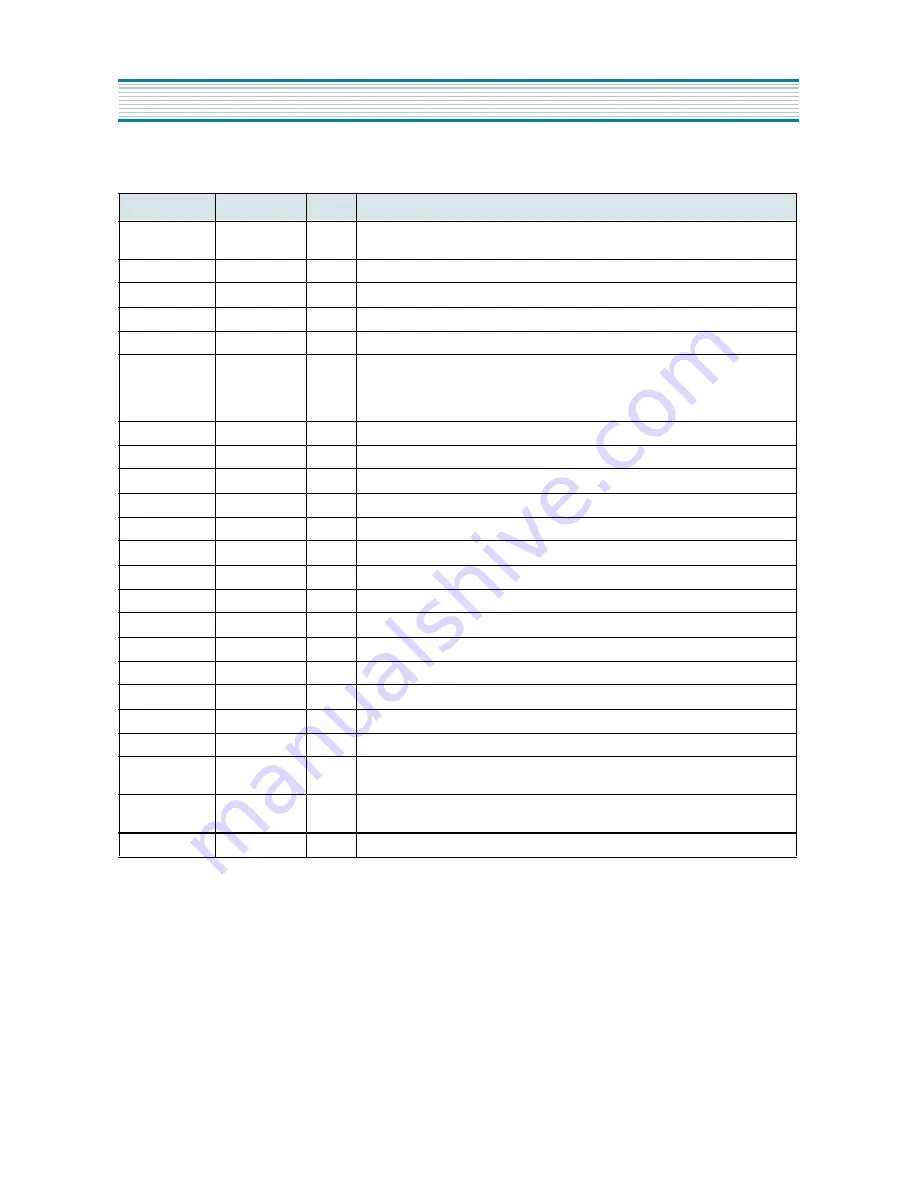
(4) Pin Description
S : supply, I : input, O : output, TTL : digital (TTL)
Pin No.
Name
Type Description
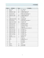
2,8,24,26,41,55
,57
S
Supply voltage ( = 0V)
9,25,40,56
S
Supply voltage ( = 5V)
42,...,49
YIN0 ... 7
I/TTL
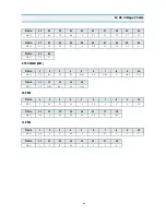
Data input Y (
see data format
)
36,...,39
UVIN4 ... 7
I/TTL
Data input UV (
see data format
)
30
SYNCEN
I/TTL
Synchronizarion enable input
31
RESET
I/TTL
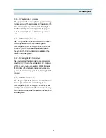
System reset. The RESET input is low active.
In order to ensure correct operation a “Power On Reset” must be performed. The
RESET pulse must have a minimum duration of two clock periods of the system
clock (LL2CLK).
23
HIN
I/TTL
H-Sync input
22
VIN
I/TTL
V-Sync input
21
SDA
I/O
- Bus data line
20
SCL
I
- Bus clock line
19
TESTIN
I/TTL
Test input, connect to for normal operation
18
TESTEN
I/TTL
Test enable input, connect to for normal operation
13,...10
UVOUT4
O/TTL
Data output UV (
see data format
)
7,...,3,1,64,63
YOUT0 ... 7
O/TTL
Data output Y (
see data format
)
62
HREF
O/TTL
Horizontal active video output
61
VOUT
O/TTL
V-Sync output
60
HOUT
O/TTL
H-Sync output
59
INTERLACED
O/TTL
Interlace signal for AC coupled vertical deflection
58,51
LL2CLK
I/TTL
System clock
50
TEST
I/TTL
Test input, connect to for normal operation
27,28,,29,52,53
,54
TESTO 4 ... 9
O
Do not connect, Pin have to be left open
14,15,16,17
TESTO 0 ... 3
O
Not used output stages, do not connect to any other driver, or ; Pins can be
left open
32, 33, 34, 35
TESTIO...3
I
Input stages (internal pull-down) ; Pins can be left open
V
DD
V
SS
V
SS
V
DD
I C
2
I C
2
V
SS
V
SS
V
SS
V
SS
V
DD
Summary of Contents for DTJ-28G8F
Page 6: ...5 3 Circuit Block Diagram...
Page 7: ...6 4 Alignment Instructions 4 1 User Remocon R 22D05...
Page 8: ...7 R 23D05 Alignment Instructions...
Page 15: ...14 3 Block Diagram IC description...
Page 24: ...23 3 Block Diagram IC description...
Page 50: ...49 Mechanical Exploded View 5 DTJ 28G7F...
Page 52: ...51 10 Printed Circuit Board...
Page 53: ......

