27
IC description
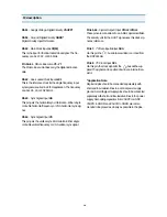
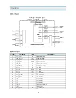
Together with this pin, it can be used to drive symmetrical
deflection amplifiers.
Pin 21
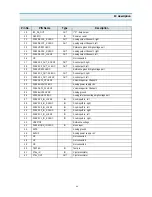
- East/West Parabola Output
EW
This pin supplies the parabola signal for the East/West
correction. The drive signal is generated with 15-bit preci-
sion. The analog voltage is generated by a 4-bit current
DAC with external resistor and uses digital noise-shaping.
Pin 22
- DAC Current Reference
XREF
External reference resistor for DAC output currents, typical
10 k
§
Ù
, to adjust the output current of the D/A converters.
(see recommended operation conditions).
This resistor has to be connected to analog fround as
closely as possible to the pin.
Pin 23
- Scan Velocity Modulation Output
SVM
This output delivers the analog SVM signal. The D/A con-
verters. At zero signal the output current is 50% of the
maximum output current.
Pin 24,25,26
- Analog RGB Output
ROUT, GOUT, BOUT
These pins are the analog Red/Green/Blue outputs of the
back-end. The outputs are current sinks.
Pin 27
- Ground, Analog Back-end
GNDO*
This pin has to be connected to the analog supply voltage.
No supply current for the digital stages should flow through
this line.
Pin 28
- Supply Voltage, Analog Back-end
VSUPO*
This pin has to be connected to the analog supply voltage.
No supply current for the digital stages should flow through
this line.
Pin 29
- DAC Reference Decouplign/Beam Current Safety
VRD/BCS
Via this pin, the DAC reference voltage is decoupled by an
external capacitor. The DAC output currents depend on
this voltage, therefore a pull-down transistor can be used
to shut off all beam currents. A decoupling capacitor of
4.7uF in parallel to 100uF (low inductance) is required.
Pin 30, 34
- Fast-Blank Input
FBLIN1/2
These pins are used to switch the RGB outputs to the
external analog RGB inputs. FBLIN1 switches the RIN1,
GIN1 and BIN1 inputs, FBLIN2 switches the RIN2, GIN2
and BIN2 inputs. The active level (Low or High) can be
selected by software.
Pin 31, 32, 33
- Analog RGB Input1
RIN1, GIN1, BIN1
These pin are used to insert an external analog RGB sig-
nal, e.g. from a SCART connector which can by switched
to the analog RGB outputs with the Fast-Blank signal.
The analog back-end provides separate brightness and
contrast settings for the external analog RGB signals.
Pin 35, 36, 37
- Analog RGB Input2
RIN2, GIN2, BIN2
These pins are used to insert an external analog RGB sig-
nal, e.g. from a SCART connector which can by switched
to the analog RGB outputs with the Fast-Blank signal.
The analog back-end provides separate brightness and
contrast settings for the external analog RGB signals.
Pin 38
- Test Input
TEST
This pin enables factory test modes. For normal operation
it must be connected to ground.
Pin 39
- Reset Input
RESQ
A low level on this pin resets the DDP 3310B.
Pin 40
- Adjustable DC Output 1
PWM1
This output delivers a DC voltage with a resolution of 8
bit, adjustable over the bus. The output is driven by a
push-pull stage. The PWM frequency is appr 79.4MHz.
For a ripple-free voltage a first order lowpass filter with a
corner frequency < 120 Hz should be applied.
Pin 41
- Adjustable DC Output 2
PWM2
See pin 40.
Pin 42
- Half-Contrast Input
HCS
Via this input pin the output level of the D/A-converted
internal RGB signals can be reduced by 6dB. Inserted
external analog RGB signals remain unchanged.
Pin 43...50
- Picture Bus Chroma
C0...C7
The Picture Bus Chroma lines carry the multiplexed color
component data. For the 4:1:1 input signal (4-bit chroma)
the pins C4...C7 are used.
I C
2
Summary of Contents for DTJ-28G8F
Page 6: ...5 3 Circuit Block Diagram...
Page 7: ...6 4 Alignment Instructions 4 1 User Remocon R 22D05...
Page 8: ...7 R 23D05 Alignment Instructions...
Page 15: ...14 3 Block Diagram IC description...
Page 24: ...23 3 Block Diagram IC description...
Page 50: ...49 Mechanical Exploded View 5 DTJ 28G7F...
Page 52: ...51 10 Printed Circuit Board...
Page 53: ......


