-37-
IC DESCRIPTION
Appendix
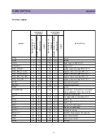
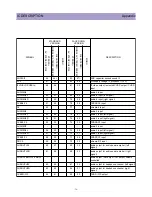
SVM
65
62
64
29
scan velocity modulation output
FBISO/CSY
66
63
63
28
ybac k input/sandcastle output or composite H/V
timing output
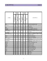
HOUT
67
64
62
27
horizontal output
VSScomb
68
70
61
21
ground connection for comb lter
VDDcomb
69
71
60
20
supply voltage for comb lter (5 V)
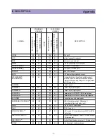
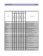
VIN (R/P
R
IN2/C
X
)
70
-
59
-
V-input for YUV interface (2
nd
R input / P
R
input
or C
X
input)
UIN (B/PBIN2)
71
-
58
-
U-input for YUV interface (2
nd
B input / PB input)
YIN (G/YIN2/CVBS-Y
X
)
72
72/-
57
19/-
Y-input for YUV interface (2nd G input / Y input
or CVBS/Y
X
input))
YSYNC
73
73
56
18
Y-input for sync separator
YOUT
74
74
55
17
Y-output (for YUV interface)
UOUT (INSSW2)
75
-
54
-
U-output for YUV interface (2
nd
RGB / YP
B
P
R
insertion input)
VOUT (SWO1)
76
-
53
-
V-output for YUV interface (general purpose
switch output)
INSSW3
77
75
52
16
3
rd
RGB / YP
B
P
R
insertion input
R/P
R
IN3
78
76
51
15
3
rd
R input / P
R
input
G/YIN3
79
77
50
14
3
rd
G input / Y input
B/P
B
IN3
80
78
49
13
3
rd
B input / P
B
input
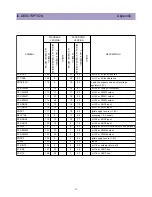
GND3
81
79
48
12
ground 3 for TV-processor
VP3
82
80
47
11
3
rd
supply for TV processor
BCLIN
83
81
46
10
beam current limiter input
BLKIN
84
82
45
9
black current input
RO
85
83
44
8
Red output
GO
86
84
43
7
Green output
BO
87
85
42
6
Blue output
SYMBOL
STANDARD
VERSION
FACE DOWN
VERSION
DESCRIPTION
A
V
STEREO QFP128
FULL-STEREO/
MONO+ A
V
STEREO SSDIP90
MONO
A
V
STEREO QFP128
FULL-STEREO/
MONO+ A
V
STEREO SSDIP90
MONO
Summary of Contents for DTQ-29U1SCV
Page 7: ...6 CIRCUIT BLOCK DIAGRAM...
Page 27: ...26...
Page 28: ...27...
Page 31: ...30...
Page 32: ...31...
Page 33: ...32...

